Bender RC48C Handbuch - Seite 4
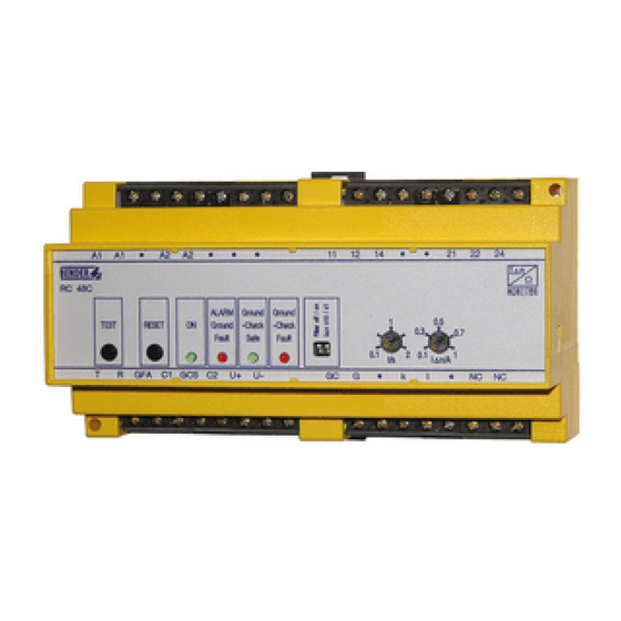
Blättern Sie online oder laden Sie pdf Handbuch für Monitor Bender RC48C herunter. Bender RC48C 8 Seiten. Ground-fault ground-continuity monitor

Anschluss
Schließen Sie das RC48C wie im folgenden Anschlussbild be-
schrieben an.
NGR
optional
Legende zum Anschlussbild
NGR
Erdungswiderstand (Neutral grounding resistor).
K2
Externer Leistungsschalter schaltet überwachtes Sys-
tem im Falle eines Alarms ab.
CT
Messstromwandler. Positionieren Sie den Messstrom-
wandler wie im Anschlussbild dargestellt.
Führen Sie nur die aktiven Leiter (alle Phasen und falls
vorhanden den N-Leiter) durch den Messstromwand-
ler. Die Leiter G (Ground) und GC (Ground check)
dürfen nicht durch den Messstromwandler ge-
führt werden.
Schließen Sie den Messstromwandler an die Klem-
men k und l des RC48C an.
Keiner der Wandleranschlüsse darf geerdet werden.
Ein Überspannungsschutz ist im Messstromwandler
integriert.
E6...
Endglied zum Abschluss der Leiter G (Ground) und GC
(Ground check) des Kabels. Ordnen Sie das Endglied
immer am Ende des Kabels in der Nähe des elektri-
schen Verbrauchers an.
Schließen Sie den Kontakt G des Endglieds an das Ge-
häuse des elektrischen Verbrauchers an. So stellen Sie
sicher, dass auch die niederohmige Verbindung zwi-
schen Gehäuse des Verbrauchers und Erde über-
wacht wird.
E6S-T
Endglied. Funktion wie E6..., jedoch mit zusätzlicher
Möglichkeit zum externen Test über einen Öffnerkon-
takt.
Schließen Sie die Kontakte G und GC wie beim E6...
beschrieben an. Verbinden Sie nun zusätzlich die
Kontakte GC und T mit dem externen Öffner.
Wird der externe Öffner betätigt, so wird im RC48C ein
Alarm Ground Check ausgelöst. Das Alarmrelais schal-
tet über den angeschlossenen Leistungsschalter den
angeschlossenen Stromzweig des Systems aus.
4
U
S
Connection
Connect the RC48C as described in the diagram below.
Legend to wiring diagram
NGR
Neutral grounding resistor
K2
External load switch, disconnects the monitored sys-
tem in case of an alarm.
CT
Residual current transformer. Position the residual
current transformer as shown in the wiring diagram.
Route only the active conductors (all phases and the
N conductor, if available) through the residual current
transformer. The conductors G (Ground) and GC
(Ground Check) must not be routed through the
transformer.
Connect the transformer to the terminals k and l of
the RC48C.
None of the CT connections may be grounded. An ov-
ervoltage protection is integrated in the residual cur-
rent transformer.
E6...
Termination device to terminate conductors G
(Ground) and GC (Ground check) of the cable. Always
position the termination device at the end of the
cable near to the electrical load.
Connect contact G of the termination device to the
enclosure of the electrical load to ensure that the low-
resistance connection between enclosure and
ground will also be monitored.
E6S-T
Termination device. The same function as E6..., but
additionally provided with external test function by
means of NC contact.
Close contacts G and GC as already described at E6...
In addition, connect contacts GC and T to the external
NC contact.
If the external NC contact is actuated, an Alarm
Ground Check is triggered in the RC48C. The alarm re-
lay disconnects the connected circuit of the system
via the connected load switch.
L1
PW
L2
L3
EGC
Querschnitt Leitung
Cross section trailing cable
RC48C_D00318_02_M_DEEN/07.2020
