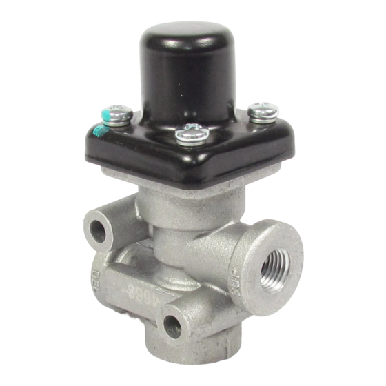
BENDIX PR-4 Handbuch - Seite 2
Blättern Sie online oder laden Sie pdf Handbuch für Kontrolleinheit BENDIX PR-4 herunter. BENDIX PR-4 4 Seiten. Pressure protection valves
Auch für BENDIX PR-4: Einbauanleitung (4 seiten)

OPERATION
Air entering the supply port is blocked from flowing out the
delivery port by the inlet valve, which is normally held closed
by the pressure regulating spring above the piston. When
sufficient air pressure builds beneath the piston, the piston
will move, opening the inlet valve and allowing air to flow out
the delivery port. As long as air pressure at the supply port
remains above the specified closing pressure, the inlet valve
will remain open.
™
NOTE: The PR-2
and PR-4
noted on the label affixed to the valve. Opening
pressures of the valves are higher than closing
pressures. The pressure ranges are noted below:
™
PR-2
valve Opening pressure 15-20 psi higher than
closing pressure.
™
™
PR-3
& PR-4
valves Opening pressure approx.
10 psi higher than closing pressure.
PR-3
™
valve Check valve will retain maximum
pressure in downstream reservoir.
If system air pressure decreases below the specified closing
pressure, the regulating spring will close the inlet valve. The
remaining air pressure at either the supply or delivery side,
(depending on where the pressure drop occurs) will be
retained.
PREVENTIVE MAINTENANCE
Important: Review the Bendix Warranty Policy before
performing any intrusive maintenance procedures. A warranty
may be voided if intrusive maintenance is performed during
the warranty period.
No two vehicles operate under identical conditions, as a
result, maintenance intervals may vary. Experience is a
valuable guide in determining the best maintenance interval
for air brake system components. At a minimum, the PR valves
should be inspected every 6 months or 1500 operating hours,
whichever comes first, for proper operation. Should the PR
valves not meet the elements of the operational tests noted
in this document, further investigation and service of the
valve may be required.
OPERATING AND LEAKAGE CHECKS
OPERATING CHECKS
1. Provide a pressure gauge and drain valve at the supply
side and delivery side of the pressure protection valve
being checked.
2. Charge the air system to full pressure and shut off the
engine.
2
™
valves closing pressure is
3. Observing the gauges on the supply and delivery sides
of the valve, slowly exhaust pressure from the delivery
side. Note that both gauges will show pressure loss until
the closing pressure of the pressure protection valve is
reached.
The pressure protection valve should close at
approximately (± 5 psi) the pressure indicated on the
valve's label or in the vehicle handbook. The gauge on
the delivery side of the valve should continue to show
loss of pressure while the gauge on the supply side
should stop at the same pressure as the setting of the
valve.
™
4. (PR-3
valve only) Build pressure up again and shut off
engine. Slowly exhaust air from the supply side of the
PR-3
™
valve. The gauge on the delivery side of the valve
should remain at the highest pressure previously attained.
LEAKAGE CHECKS
1. Charge the air system to full pressure and shut off the
engine.
2. Apply a soap solution around the cap of the pressure
protection valve. A 1" bubble in 3 seconds or longer is
acceptable. PR-3
™
valve - No leakage is permissible at
the bottom of the valve.
3. Drain the air pressure from the delivery side of the
pressure protection valve and disconnect the air line to
it.
4. Apply a soap solution to the delivery port. A 1" bubble in
5 seconds or more is acceptable.
GENERAL
If the pressure protection valve does not function as
described, or leakage is excessive, it is recommended that
it be replaced with a new or remanufactured unit or repaired
with genuine Bendix parts available at Bendix outlets.
REMOVING AND INSTALLING
REMOVING
1. Block or hold the vehicle by means other than air brakes.
2. Drain all system reservoirs to 0 psi.
3. Disconnect and identify (supply and delivery) the air
lines leading to and from the pressure protection valve.
4. Remove the mounting bolts, if any, that secure the valve.
INSTALLING
1. Re-install the mounting bolts and secure the replacement
valve to the vehicle.
2. Reconnect the supply delivery air lines to the proper
ports of the replacement valve.
