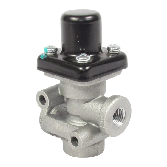
BENDIX PR-4 Einbauanleitung - Seite 3
Blättern Sie online oder laden Sie pdf Einbauanleitung für Kontrolleinheit BENDIX PR-4 herunter. BENDIX PR-4 4 Seiten. Pressure protection valves
Auch für BENDIX PR-4: Handbuch (4 seiten)

REMOVAL
Before removing the valve, park the vehicle and drain the air
system completely, follow the safety guidelines on page 2.
1. To aid in the installation of the valve, mark the air lines
and their respective ports before disconnecting.
2. Remove and retain the mounting hardware.
3. Remove the valve from the vehicle.
DISASSEMBLY
1. Remove the four (4) round head machine screws while
holding the spring retainer to the body. Remove the
spring retainer.
The spring retainer is under a spring load and must
be removed carefully.
2. Remove and retain the spring(s) under the retainer for
reuse.
NOTE: Some Bendix
®
and Bendix
PR-4
Pressure Protection Valves have
®
™
only one (1) spring and some will have two (2).
3. Remove and discard the piston assembly.
NOTE: This would conclude the disassembly procedure
for a PR-4 pressure protection valve (Figure 2). The
following steps are for the PR-3 reservoir control valve
(Figure 1).
4. Discard the retaining ring.
5. Remove and reuse the o-ring retainer.
6. Remove and discard the o-ring, spring, and check valve.
ASSEMBLY
NOTE: Prior to the assembly of new parts into the valve,
clean the internal passages with a suitable solvent and dry
thoroughly. Grease all o-rings, o-ring grooves, bores, and
pistons using the lubricant supplied with this kit.
1. Install the piston assembly in the valve body.
2. Position the spring(s) on the piston and install the spring
retainer.
3. Secure the spring retainer using the four (4) round head
machine screws. Torque the screws to 20-30 in-lbs
(2.3-3.4 N•m).
This completes the reassembly of the PR-4
pressure protection valve. Proceed to step 4 for the
PR-3 reservoir control valve.
4. Install the spring on the check valve and install in the
valve body.
5. Install the o-ring in the valve body.
6. Install the o-ring retainer taking care that the spring
fits in the protrusion provided on the o-ring retainer
(See Figure 1).
7. Install the retaining ring.
PR-3
Reservoir Control Valves
™
INSTALLATION
1. Clean the air lines connecting to valve.
2. Inspect all lines and/or hoses for damage and replace
as necessary.
3. Install the valve and tighten the mounting bolts.
4. Connect the air lines to the valve.
OPERATING AND LEAKAGE CHECKS
OPERATING CHECKS
1. Provide a pressure gauge and drain the valve at the
supply side and delivery side of the pressure protection
valve being checked.
2. Build up the air system to full pressure and shut off the
engine.
3. While watching the gauges on the supply and delivery
sides of the valve, slowly begin to exhaust pressure
from the delivery side. Note that both gauges will show
pressure loss until the closing pressure of the pressure
protection valve is reached.
The pressure protection valve should close within ±5 psi
of the pressure indicated on the valve's label or in the
vehicle handbook. The gauge on the delivery side of the
valve should continue to show loss of pressure while
the gauge on the supply side should stop at the same
pressure as the setting of the valve.
4. (PR-3 reservoir control valve only) Build pressure up
and slowly exhaust air from the supply side of the PR-3
reservoir control valve. The gauge on the delivery side
of the valve should remain at the highest pressure
previously attained.
LEAKAGE CHECKS
1. Build up the air system to full pressure and shut off the
engine.
2. Apply a soap solution around the cap of the pressure
protection valve. A one (1) in. (2.54 cm) bubble in three
(3) seconds or longer is acceptable. No leakage is
permissible at the bottom of the PR-3 reservoir control
valve.
3. Drain the air pressure from the delivery side of the
pressure protection valve and disconnect the air line
to it.
4. Apply a soap solution to the delivery port. A one (1)
in. (2.54 cm) bubble in five (5) seconds or longer is
acceptable.
3
