BENDIX R-12V Installationsanleitung Handbuch - Seite 3
Blättern Sie online oder laden Sie pdf Installationsanleitung Handbuch für Kontrolleinheit BENDIX R-12V herunter. BENDIX R-12V 6 Seiten. Universal service replacement relay valves kit
Auch für BENDIX R-12V: Handbuch (6 seiten)

CHANGEOVER INFORMATION
BENDIX
R-12
& R-14
®
®
The R-12
(H & V) and the R-14
®
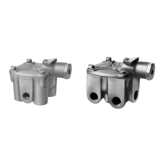
installation instructions. The R-12 and R-14 relay valves are available with either two (2) horizontal delivery ports or four (4)
vertical delivery ports. The R-12 and R-14 can be used in either service or spring brake control systems and in addition
can be used to replace anti-lock modulators when the anti-lock system is reverted to a straight service brake system. The
R-12 and R-14 relay valves are similar in appearance. The difference between them is the R-14 incorporates a balance
port which provides the added feature of built in anti-compounding when the R-14 is used to control the emergency
section of the spring brakes. Refer to the chart below to select the appropriate R-12 or R-14 relay valve.
Bendix R-1
®
Fig. 1
Bendix R-10
®
Fig. 5
Midland
KN28010, 28010A
®
Fig. 9
Midland 28160
Fig. 13
UNIVERSAL REPLACEMENT RELAY VALVES
®
(H & V) universal replacement valves include mounting bracket Pc. No. 296010 and
®
Bendix R-5
®
Fig. 2
Berg
12342, 12343, 12344
®
Fig. 6
Midland KN28060, 28060A
Fig. 10
Sealco
A1100
®
Fig. 14
Bendix R-6
®
Fig. 3
Berg 12345, 12346
Fig. 7
Midland KN28130
Fig. 11
Sealco 9125 Series
Fig. 15
Bendix R-8
®
Fig. 4
Kelsey Hayes
®
Fig. 8
Midland 28140
Fig. 12
Wagner
RG-2
®
Fig. 16
3
