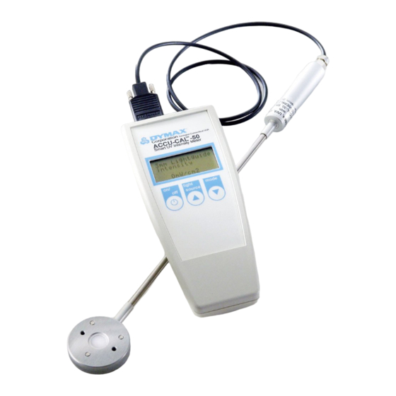
dymax ACCU-CAL 50-LED Benutzerhandbuch - Seite 10
Blättern Sie online oder laden Sie pdf Benutzerhandbuch für Messgeräte dymax ACCU-CAL 50-LED herunter. dymax ACCU-CAL 50-LED 16 Seiten. Led radiometer

2. Select the measurement mode appropriate for the data
required and take readings. To improve accuracy, it is
suggested that multiple measurements be taken and
averaged.
•
Direct readings at 0-mm working distance for repeatable
measurements:
1.
With the adapter installed, align the radiometer sensor
by nesting the emitter faceplate onto the adapter tabs
to ensure precise engagement (Figure 14).
2.
Keep the sensor and emitter square to each other and
activate an exposure cycle of the emitter.
3.
Take intensity reading after 5-10 seconds to allow for
output stabilization.
4.
To avoid possible damage to the radiometer sensor,
allow the sensor to cool between measurements and
do not expose the sensor to energy emissions for more
than 15 seconds.
Testing the BlueWave
1.
Attach the detector to the radiometer (Figure 15).
2.
Attach the BlueWave QX4 optic adapter to the detector (Figure 16) using the two 2-mm screws provided.
Note: The optical adapter and optometer are calibrated as a set, so they are not interchangeable among other similar
type radiometers.
3.
Insert the LED head into the optic adapter until it bottoms out. Tighten the set screw on the top of the optic adapter
when the LED head is installed.
Note: Do not over tighten the set screw, as damage to the LED head may occur.
Figure 15.
Attach Detector
4.
Press and release the On/Off button on the radiometer's face plate to turn the unit on.
5.
On the radiometer's display, the top line displays the light source and the second line displays the mode.
10
QX4
®
Figure 16.
Attach Optic Adapter to Detector
Figure 14.
Adapter Alignment
Figure 17.
Insert LED Head into Optical Adapter
U S E R G U I D E
A C C U - C A L ™ 5 0 - L E D R A D I O M E T E R
|
