GAC ESD-5555 Technische Informationen - Seite 12
Blättern Sie online oder laden Sie pdf Technische Informationen für Kontrolleinheit GAC ESD-5555 herunter. GAC ESD-5555 12 Seiten. Speed control unit
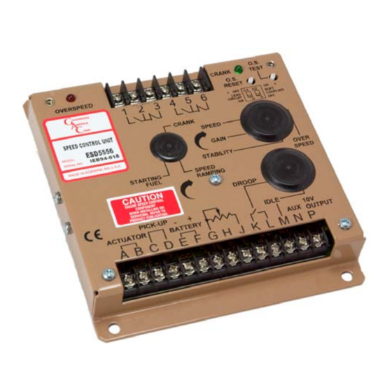
Slow instability can have many causes. Adjustment of the GAIN and STABILITY usually cures
most situations by matching the speed control unit dynamics. If this is unsuccessful, the dead time
compensation can be modified. Add a capacitor from posts E2 to E3 (negative on E2). Post
locations are illustrated in Diagram 1. Start with 10 mfds. and increase until instability is
eliminated. The control system can also be optimized for best performance by following this
procedure.
If slow instability is unaffected by this procedure, evaluate the fuel system and engine
performance. Check the fuel system linkage for binding, high friction, or poor linkage. Be sure to
check linkage during engine operation. Also look at the engine fuel system. Irregularities with
carburetion or fuel injection systems can change engine power with a constant throttle setting.
This can result in speed deviations beyond the control of the governor system. Adding a small
amount of droop (Jumper K-L) can help stabilize the system for troubleshooting.
NON-PERIODIC instability should respond to the GAIN control. If increasing the gain reduces the
instability, then the problem is probably with the engine. Higher gain allows the governor to
respond faster and correct for disturbance. Look for engine misfirings, an erratic fuel system, or
load changes on the engine generator set voltage regulator. If the throttle is slightly erratic, but
performance is fast, move switch C1 to the "OFF" position. This will tend to steady the system.
If unsuccessful in solving instability, contact for assistance.
In order to be compliance with the CE directives, the installer is obligated to install the
equipment in strict accordance with the following guidelines.
1.
The Speed Control Unit must be mounted against the metal ground plane with four bolts which make
a positive electrical connections between the case and the back plane or a backing plate, PL128 must
be installed.
The magnetic pickup must be connected to the speed control using shielded cable as shown in the
2.
wiring diagrams.
All shielded cable connections to the speed control must be connected to the case at the corner
3.
threaded connection per the wiring diagram.
The BATTERY minus connection at Terminal E must also be additionally jumpered to the case at the
4.
corner.
Shielded cable for the actuator is recommended to minimize the actuator's slight movement during
5.
fast voltage transients. The installer's choice of not using shielded cable may cause the actuator to
move more than slightly during these transients. However, no failures should be experienced.
The installer must refer to the wiring diagram in the literature for proper electrical connects.
6.
Technical Information