GAC ESD5300 Series Handbuch - Seite 7
Blättern Sie online oder laden Sie pdf Handbuch für Kontrolleinheit GAC ESD5300 Series herunter. GAC ESD5300 Series 9 Seiten. Speed control unit
9
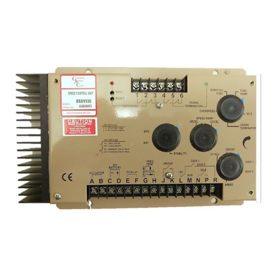
ADDITIONAl FEATURES (CONTINUED)
aDJUSTaBLe cHoPPInG freQUencY
The actuator chopping frequency can be varied using the potentiometer labeled CF ADJ. This
chopping frequency applied to the actuator provides an additional stability enhancement as
the dither shakes the actuator to overcome static friction and ensure its immediate response.
overSPeeD monITor
The overspeed monitor circuit trip point is set by the multi-turn potentiometer.
•
Set overspeed by raising the engine speed to the specific trip point speed and turning
the OVeRSPeeD adjustment CCW until the overspeed circuit turns ON (Red leD).
This will also turn off the actuator output circuit and change the state of the internal
relay contacts at Terminals 1, 2, 3.
•
To reset the overspeed circuit, push the ReSeT switch through the hole provided or
cycle the DC power to the unit. The Test switch will reduce the overspeed setting about
20%. If the engine is running at rated speed and the Test button is pushed the over-
speed monitor circuit should trip.
The relay contacts at Terminals 1, 2, 3 should be used to turn off the engine, either fuel or
air.
Do not rely on time control to turn off the actuator as a means of shutting off the
engine. A fault could have occurred in the actuator, linkage, cables, etc. which the
eSD5300 does not control.
cranK TermInaTIon
When no power is applied to the eSD5300, the crank relay contacts, Terminals 5 and 6,
are normally closed.
As the speed increases, the internal relay will change state and the green leD will light.
The speed setting at which the leD lights is determined by the multi-turn CRANK TeRMI-
NATION speed setting potentiometer.
Adjust CRANK TeRMINATION CW to increase the speed at which this transition takes
place.
Once the circuit has tripped, the crank termination circuit will remain tripped until DC power
is removed from the unit. This will reset the function.
fInaL SPeeD SeTTInG
After the Droop, Frequency Trim, and/or accessory inputs have been connected, readjust the operating SPeeD and IDle.
7
ESD5300 Speed Control Unit 09-2020-H
Governors America Corp. © 2020 Copyright All Rights Reserved
PIB1041