GAC EEG6500 Handbuch - Seite 2
Blättern Sie online oder laden Sie pdf Handbuch für Controller GAC EEG6500 herunter. GAC EEG6500 9 Seiten. Enhanced electronic governor with quikset display
4
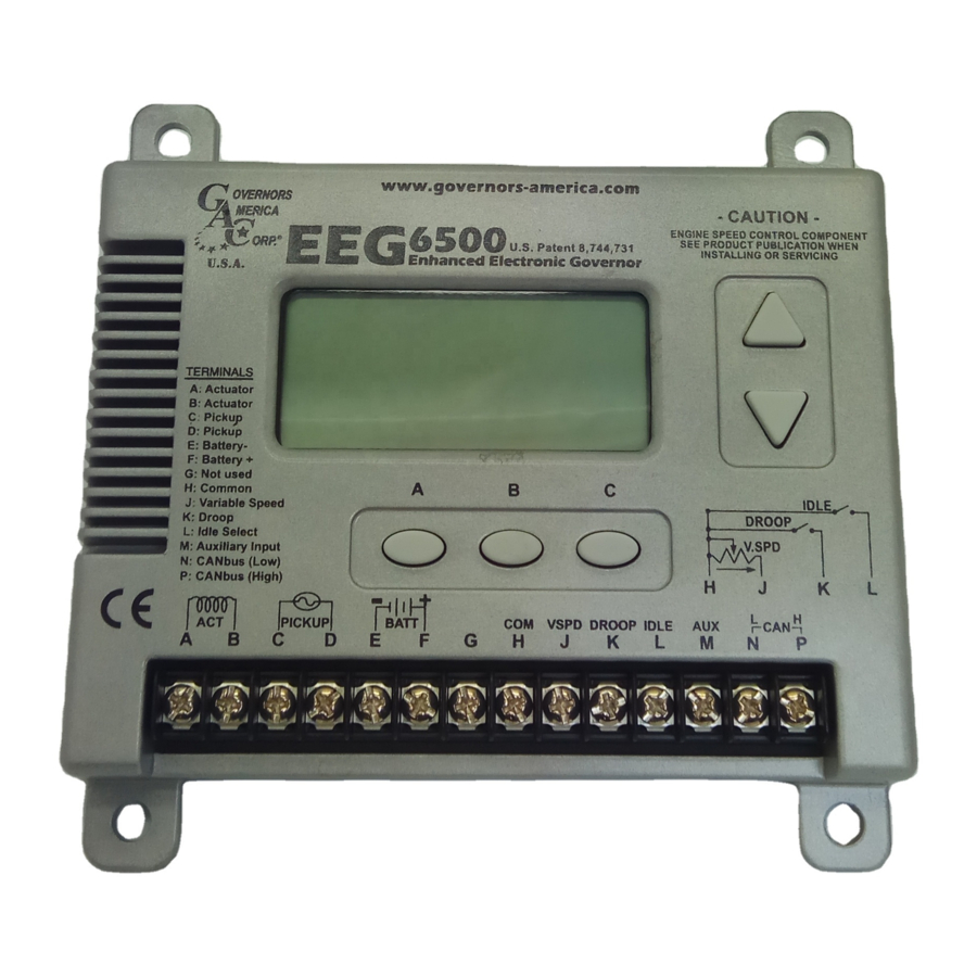
WIRING
TERM
DEFINITION
Actuator (+)
A
Actuator (-)
B
C
Magnetic Pickup (+)
D
Magnetic Pickup (-)
E
Battery (-)
F
Battery (+)
H
Ground Signal
J
Variable Speed Input
K
Droop Select
L
Idle Select
M
Aux Input
N
CAN L
P
CAN H
RECOMMENDATIONS
WARNING
Loss of Magnetic Pickup Sensing
If EEG detects no input from the magnetic pickup, the EEG
will set the actuator to 0V and set the speed to 0 RPM. The
display will flash the RPM along with the Warning Indicator.
Parameters will be unchangeable.
5
DISPLAY & CONTROLS
Parameter Value
Displays the value of a selected parameter or live
running parameter. This
area will blink if a system
shutdown and restart is
required.
Secondary Parameters
Pressing either the UP or DOWN arrow allows you to tog-
gle through the five secondary parameters: Engine Speed
(RPM), Duty Cycle (%), Actuator Current (Amps), Engine
Speed (Hz) and Variable Speed (%)
Tap
or
Overcurrent
If the EEG detects an actuator overcurrent it will
terminate power to the actuator, the display will
flash Actuator Current along with the warning
indicator. (Cycle power to restart)
Fuel Limit
If the EEG detects that the FUEL LIMIT setting
has been exceeded, the display will flash the
FUEL LIMIT along with the warning indicator.
Paramters will be unchanged.
Over Speed
"Over Speed" will blink when the unit is in overspeed.
(Cycle power to restart)
Lock Feature
Once the LOCK parameter on the main menu is enabled
("ON"), the display can be manually unlocked.
Locking/Unlocking the Display
Press and hold both the UP and DOWN arrows simultane-
ously for 3 seconds to UNLOCK or to LOCK the display.
GAUGE
NOTES
AWG / mm
2
#16 / 1.31
#16 / 1.31
* Twisted wires 14 turns per foot.
#20 / 0.52
0.02in (.51mm) gap between sen-
#20 / 0.52
sor and gear teeth.
#16 / 1.31
A 15 amp fuse must be installed
in the positive battery lead to pro-
#16 / 1.31
tect against any overload or short
circuit
Reference for variable speed/trim
#16 / 1.31
input & switches
5K Ω Resistive, 0-2.5 VDC or
#20 / 0.52
4-20mA. Increasing Voltage. Resis-
tance or Current Increases Speed
Active when connected to Terminal
#16 / 1.31
H
Active when connected to Terminal
#16 / 1.31
H
Load sharing / synchronizing, 5V
#20 / 0.52
nominal (0-10V), reverse ramp
#20 / 0.52
Twist wires 14 turns per foot.
#20 / 0.52
Row 2 Column 3
Ground to Case
5K Ohm Resistive Speed Trim Pot.:
A
B
C
D
A
E
0-2.5 Volt or 4-20mA* Variable Speed Input:
* 4-20mA input requires an external 200 Ohm
resistor across Terminals H & J
IMPORTANT:
When installing, be sure there's a good connection between
the case of the EEG6500 and chassis / battery ground.
Parameter Units
Displays the units for the parameter (e.g. RPM)
Quikset Menu
One row of parameters is displayed at a time.
EEG6500 Enhanced Electronic Governor 05.09.18
2
A
B
C
D
E F
Actuator
Magnetic
Speed
Pickup
-
+
Battery
(12V or 24V)
5K
Variable Speed / Trim
Potentiometer
B
F
C
G
D
H
E
J
F
K
G
L
VSPD
Droop
COM
Idle
Parameter Adjust
Parameter
Adjust Up
Increment a Parameter Value:
HOLD
Parameter
Adjust
Down
Column Select Buttons
A
To change the displayed row of parameters:
Tap any
To view a parameter value in a selected row:
Hold
For: SPEED
For: IDLE
For: FUEL LIM
© 2018 Copyright All Rights Reserved
N P
120 Ohms
( End of CAN bus)
H
M
J
N
K
P
L
M
N
Ground to
Case
CAN J1939
( Optional )
Accessory
Input
Ground to
Case
and TAP
or
Rapidly Increment a Value:
HOLD
and HOLD
or
B
C
Hold: Button A
Hold: Button B
Hold: Button C
PIB 5010 F
P