GAC LSM201N Handbuch - Seite 7
Blättern Sie online oder laden Sie pdf Handbuch für Controller GAC LSM201N herunter. GAC LSM201N 11 Seiten. Load sharing modules
5
INITIAL ADjUSTMENTS (CONTINUED)
REvERSE POWER MONitOR (CONtiNUED)
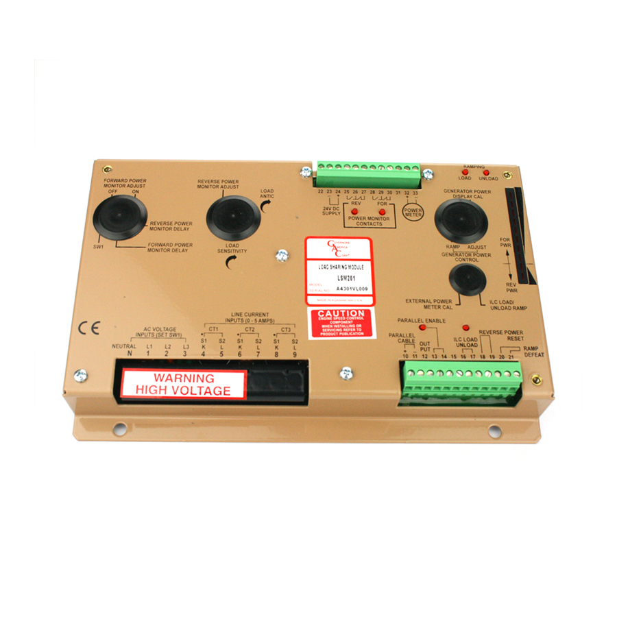
Solder a jumper wire across these posts without damaging the circuit board. When a reverse power condition occurs, the internal relay will
activate and latch. To reset the relay, open the external Reverse Power Relay switch between Terminals 18 and 19.
The reverse power monitor also offers a time delay adjustment. The time delay is an inverse function where the higher
the reverse power, the shorter the delay in the monitor's operation. This provides faster response if a major reverse
power condition occurs. Set the time delay to the shortest delay (maximum CCW) unless a long delay is required.
10 A Form C NO and NC relay contacts are provided at Terminals 25, 26, and 27 to operate the external protection
mechanisms that remove the generator from service once a reverse power condition has occurred. LEDs signal the
reverse power monitor relay's condition.
use caution in setting the reverse power adjustment to prevent damage to the generator from excessive delay
PARAllEliNG WitH OtHER GAC lOAD SHARiNG MODUlE
The LSM200 Series may be used with other types of GAC load sharing modules, where an external mains auxiliary parallel cable relay
already exists. Connect Terminals 13 and 14 together permanently, closing the internal parallel cable relay and treat the parallel cable
as external series contacts.
NOtE: The smooth ramping function during paralleling will not be available under these circumstances.
DROOP
The LSM200 Series operate as isochronous systems, with no internal available droop. Droop can be required add 1 MΩ across the
parallel cable to add <1% droop. Lower values of resistance with provide increased values of droop.
NOtE: If droop is used, the automatic load/unload individual load control functions will not operate.
ilC (iNDiviDUAl lOAD CONtROl) AND lOAD RAMPiNG
Individual generator control is a main function of the LSM200 Series. Opening and closing a switch at Terminals 16 and 17 loads and
unloads the generator. Two LEDs (LOAD and UNLOAD) indicate the status for the operator. The Typical operation is:
•
When a group of engines are operating together in a load sharing mode, and one engine needs to be removed from service, the
ILC unload switch is closed (Terminals 16 and 17).
•
The selected generator will start to reduce power until it gives up all its load and is held at zero power at which time it can be re-
moved from service by opening its generator circuit breaker.
•
The speed at which the unit reduces its load is controlled by the ILC LOAD l UNLOAD RAMP adjustment. This control adjusts the
unloading rate, and thus the smoothness, at which the load transition occurs.
•
The generator can be held at zero power indefinitely. If the ILC switch is opened, the generator will increase its load and smoothly
ramp back up to normal power.
Once a generator is removed from service, the ILC switch must be opened so the system will smoothly parallel and accept load when
the generator is put back into service. When re-paralleling a generator set (ILC open), the LSM201 will match the existing parallel cable
voltage with its own so that a smooth connection is made (zero voltage difference). The load control will ramp to equal load sharing. See
details in
Load Sharing
Mode.
lOAD ANtiCiPAtiON FUNCtiON
The load anticipation function improves the governor response to loads applied to parallel generators. The basic transient response of
the system is improved because the electrical load is measured directly by the LSM. This load occurs before the speed changes and
thus the response delays are reduced. The internal LOAD ANTICIPATION adjustment allows the operator to adjust the magnitude of
the response to the load change that is presented to the governor. A CW adjustment increases the magnitude of the compensation.
Transient reductions of 10 - 30 % are possible if the capability of the engine is not limiting the system. Optimize this adjustment with
repetitive load steps.
MAiNS POWER CONtROl
The generator power control feature is intended to be used when the generator is supplying power to the infinite main bus (exporting
power). See Section 4 Wiring diagrams. In this mode, a temporary connection is made across the parallel cable at Terminals 10 and 11.
After synchronizing and paralleling to the mains, the parallel enable switch (Terminals 13 and 14) must be closed when the main generator
circuit breaker is closed.
The GENERATOR POWER CONTROL Adjustment can be turned CW toward 100. This will cause the generator to start supplying power
to the mains. The generator power output is a function of how far the ADJUST control is turned CW and how high the load sensitivity con-
trol is adjusted. Once this setting is made, the power output can be reduced to zero with a switch connection between Terminals 15 and
16. The power setting can also be set externally with a simple potentiometer and a switch that applies a voltage to Terminal 15.
This power control function can be ramped for smooth operation. Adjustment of the RAMP control towards 100 will slow down the load
pickup time. The load up and load down times are about the same. For fast response, temporarily connect Terminals 20 and 21.
LSM200 Series Load Sharing Modules 6-2021-B1 PIB4100
7
Governors America Corp. © 2021 Copyright All Rights Reserved