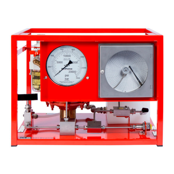
Hi-Force AHP2-036 Gebrauchsanweisung - Seite 7
Blättern Sie online oder laden Sie pdf Gebrauchsanweisung für Water Pump Hi-Force AHP2-036 herunter. Hi-Force AHP2-036 9 Seiten. Air driven hydrotest pumps

INSTRUCTION MANUAL – AIR DRIVEN HYDROTEST PUMPS:
Model Series: AHP10.AHP26, AHP36, AHP58, AHP107, AHP187, AHP275, AHP425,
AHP2-036, AHP2-060, AHP2-097, AHP2-144, AHP2-237, AHP3-040, AHP3-060, AHP3-100, ATDP63 ATDP125,
The hydraulic pressure to be generated by the
air driven pump is dependent upon the air
pressure applied i.e.
Pump ratio 216/1: 1psig air drive pressure
applied can generate 216psig hydraulic
pressure.
PREPARATION FOR USE.
It is recommended to use good quality clean &
dry air (without moisture content) to drive the air
driven pump unit. As the air pressure drops at the
pump exhaust ports, the air will cool and any
water droplets in the air can freeze prematurely
due to temperature variation. For this reason we
include and recommend the use of 'Killfrost' at
all times to be placed in the installed pump oil
lubrication bottle. The lubricator bottle drop
feed rate is advised at 1 drop per 20 pump
strokes.
If for any reason the lubricator is not used, the air
motor should be disassembled, inspected and
repacked with suitable compound grease every
1 million strokes. Silicone type grease is prone to
stiffening when not in use, at a minimum the
grease should be changed after a 6month idle
period and every 12 months in a scheduled
routine service interval at a minimum.
Connect the hydraulic pressure outlet port to
the equipment to be pressurised via a flexible
hose assembly or via a rigid pipe-work system.
Ensure that all attached hose, pipe-work and
fittings are rated suitably to match, at a
minimum, or exceed the maximum working
pressure rating of the pump unit.
Direct the provided drain hose into a suitable
container or drain.
Connect a 1" bore air supply hose to the power
pack air inlet port. Use appropriately pressure
rated air hose and fittings for this purpose, these
components must be rated at a higher working
pressure than the maximum supply air pressure
that can be applied to the power pack. (1/2"
bore air supply tubing is the smallest size that will
allow the pump to operate).
Ensure that the air on/off valve on the pump is in
the closed before switching on the air supply.
(Note: To achieve the potential maximum
working pressure and output flow capability,
ensure an air supply of 7 bar (100psi) is available
with a flow rate of 212 SCFM (6M³/min). The use
of a smaller bore air hose or a smaller SCFM
volume supply is acceptable but will diminish the
maximum potential flow-rate from the pump.
Hi-Force Limited – Prospect Way – Daventry – Northants NN11 8PL – United Kingdom
Tel: +44(0) 1327 301000: Fax: +44(0) 1327 706555: Website: www.hi-force.com
ATDP216,
Make connections to the fluid inlet port using
suitably rated hose, pipe-work and fittings and a
fluid isolation valve. The fluid inlet hose and
fittings bore is recommended to be not less than
1" bore.
(Once the pump has raised hydraulic pressure
DO NOT close the fluid inlet isolation valve).
Ensure the water supply is sufficient and only at
7 bar maximum pressure. It is advisable to ensure
clean water (fluid) is used as this prevents any
possible chance of debris contaminating the
pump check valves (Y type strainer filter built in
pump unit water line).
If fluid is being supplied from a tank ensure the
tank is sited close to the fluid inlet port on the
power pack or sited above the level of the fluid
inlet port (positive head/displacement pump).
Reducing the fluid supply inlet hose/pipe bore or
supplying water from a tank at a lower level
than the pump inlet port may cause pump
cavitation's and potential damage, so should
always be avoided. DO NOT run the pump dry,
as this will damage the hydraulic components.
PRINCIPLE STEPS OF OPERATION
1) Check that the pump on/off air valve is
closed, and that the hydraulic pressure release
valve is in the open position.
2) Adjust the pump air pressure-regulating valve
anticlockwise until it is fully wound out.
on the air supply to the pump by external
means.
3) Plug the hydraulic outlet connection.
4) Turn on the water supply to the pump. As long
as the water supply is above approximately
0.7bar (10 psi) the water will flow through the
pump and through the drain hose attached to
the pressure release valve, bleeding the system.
If not (flowing water) turn the pump air pressure-
regulating valve slowly clockwise until 15-20 psi is
shown on the air pressure regulators own air
pressure gauge, the pump will operate pumping
the inlet water supply to drain.
5) Turn the pump air on/off valve to the off
position and close the hydraulic pressure release
valve once any air bubbles, seen in the nylon
drain hose, have disappeared and the system is
bled properly.
6) To use the pump:
Open the pump air on/off valve.
Switch
