Active Silicon HARRIER Schnellstart-Handbuch - Seite 7
Blättern Sie online oder laden Sie pdf Schnellstart-Handbuch für Aufnahmegeräte Active Silicon HARRIER herunter. Active Silicon HARRIER 15 Seiten. Usb/hdmi camera interface board

(SW302). When the Power Switch (and camera power supply) is switched ON the PWR ON LED will
illuminate.
For more information please see the
(see
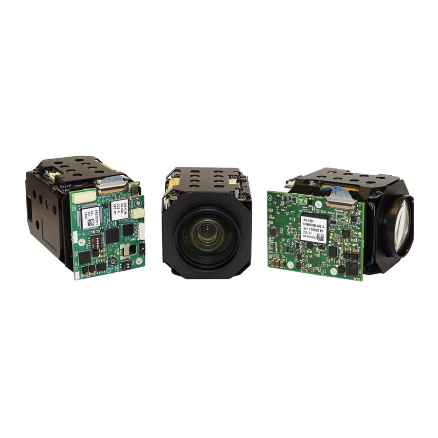
Harrier USB/HDMI Camera Interface Board
Setting up the System for Full Evaluation
To set up and get the Harrier USB/HDMI Camera Interface Board running please follow the
instructions below:
1. Connect the camera to the camera interface board connector (J1) using the 30-way micro coax
cable (connector type: KEL USL00-30L). (If you have purchased a pre-assembled camera
module, e.g. AS-CIB-USBHDMI-002-1110-A, this cable will already be connected).
2. RS-232/RS-485/TTL communications: to use serial communications with the camera, connect
the USB A - mini USB cable to the mini USB connector on the Harrier Evaluation Board, and
connect the USB A plug to a PC USB socket.
The USB PWR LED should light up indicating a live connection to the PC.
3. Connect the camera interface board PWR/CTRL connector (J3) to the Harrier Evaluation Board
PWR/CTRL connector using the 10-way cable. For:
RS-232 connect the 10-way cable to J103,
RS-485 connect the 10-way cable to J203
TTL connect the 10-way cable to either J103 or J203.
4. Connect the camera interface board I/O connector (J2) to the Harrier Evaluation Board I/O
connector (J102) using the 4-way cable.
Figure 10. Harrier Evaluation Board connected to Harrier USB/HDMI Camera Interface
Board and MP1110M camera.
March 2021
HARRIER USB/HDMI CAMERA INTERFACE BOARD
Harrier Evaluation Board datasheet
- Downloads section).
QUICK START GUIDE
Version 1.7 – March 2021
on the Active Silicon website
Page 7 of 14
