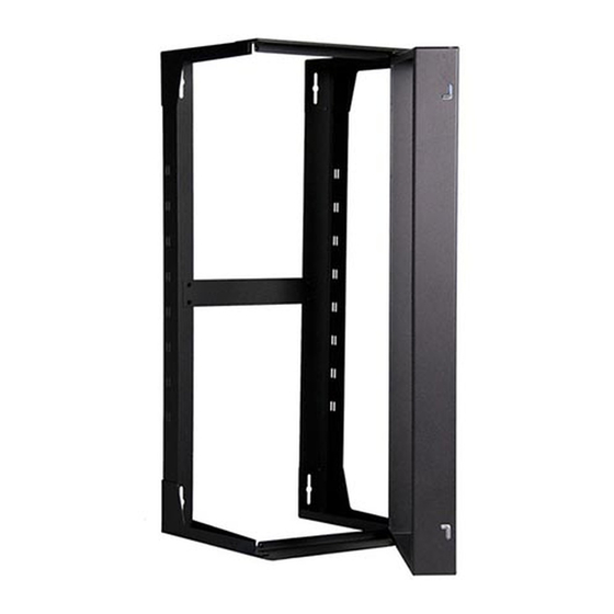
Great Lakes SR Series Installationsanleitung Handbuch - Seite 5
Blättern Sie online oder laden Sie pdf Installationsanleitung Handbuch für Racks & Ständer Great Lakes SR Series herunter. Great Lakes SR Series 8 Seiten. 19" eia wall mount swing rack
Auch für Great Lakes SR Series: Installationsanleitung Handbuch (12 seiten)

PARTS LIST: 24SR, 36SR, 48SR
COMPONENT
TOP AND BOTTOM BRACE
SWING FRAME ASSEMBLY
SIDE BRACE ASSEMBLY
REAR BRACE PANEL
#10-32 KEPS NUT WITH EXTERNAL TOOTH LOCK WASHER
#10-32 X 1/4" PHIL PAN HD SCREWS, TYPE 23, BLACK
#10-32 X 1/2" PHIL PAN HD SCREWS, TYPE 23, BLACK
1/4 - 20 X 3/4"L PHIL 82
BLACK NYLON SPACER (0.50 OD, 0.26 ID 0.187 TH)
INSTRUCTION MANUAL
TOOLS REQUIRED: 3/8" NUT DRIVER, PHILLIPS HEAD SCREWDRIVER
Special Note: Item #7 used to mount equipment to swing rack.
STEP 1
Place the back brace onto the four threaded studs on the two side brace as-
semblies. Secure with four #10-32 keps nuts. Tighten with 3/8" nut driver.
Install the top/bottom braces to the outside of the two side brace assemblies
with eight #10-32 x 1/4" Phillips Pan Head screws, but do not tighten screws.
The large formed edge of the top/bottom braces mount towards the rear and
the inside of the swing rack.
Top/Bottom Brace
(qty. 2)
Keps Nuts #10-32
threads (qty. 4)
Phillips Pan Head Screw
#10-32 x 1/4" long
O
FLAT HEAD SCREW W/NYLON LOCKING PELLET
Back Brace
(qty. 1)
QTY.
2
1
2
1
4
8
50
2
2
1
Phillips Pan
Head Screws
#10-32 x 1/4"
long (qty. 8)
Side
Brace
Assembly
(qty. 2)
Top/Bottom
Brace
5
