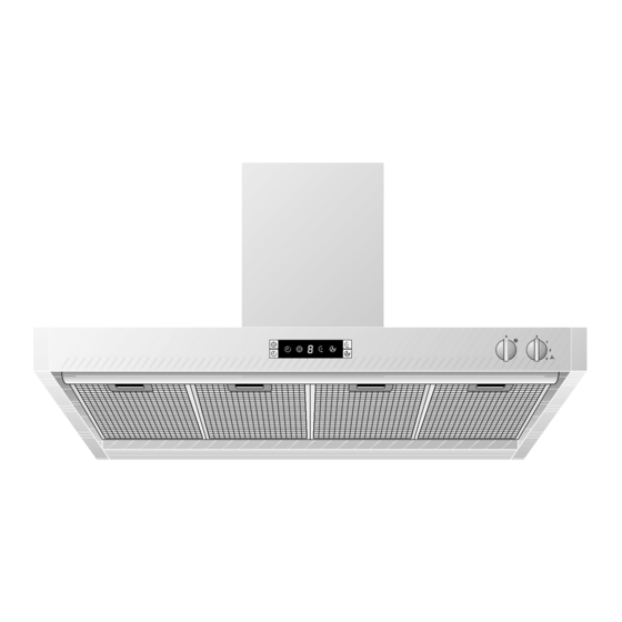
Gaggenau AH360120 Betriebs- und Montageanleitung - Seite 6
Blättern Sie online oder laden Sie pdf Betriebs- und Montageanleitung für Lüftungshaube Gaggenau AH360120 herunter. Gaggenau AH360120 17 Seiten.
Auch für Gaggenau AH360120: Betriebs- und Montageanleitung (17 seiten)

2. Structure and operating principle
2.1 Structure of the appliance
1
2
Fig. 2
5
6
10
11 12
13 14 15
Fig. 3
2.2 Accessories/special accessories
You can order the following special accessories:
– Back draught flap RK 040-150:
Back draught flap for insertion in the extractor's
blow-out opening
– Flexible aluminium pipe AR 040-150:
DN 150 up to 3.5 m length
with 2 hose clamps
All manuals and user guides at all-guides.com
3
4
7
8
9
1 Display
2 Glass plates
3 Air duct
4 Control panel
5 Grease filter key
6 Ventilation level display
7 "Coanda level" key
8 "Light" control knob
9 "Ventilation level" control knob
10 "After-running" key
11 "After-running" symbol
12 "Grease filter saturation" symbol
13 "Coanda level" symbol
14 "Intensive level" symbol
15 "Intensive level" key
Installation accessories:
LK 360-010: Ventilation duct for
ceiling heights of 2.35 - 2.66 m
LK 360-020: Ventilation duct for
ceiling heights of 2.66 - 3.00 m
5
