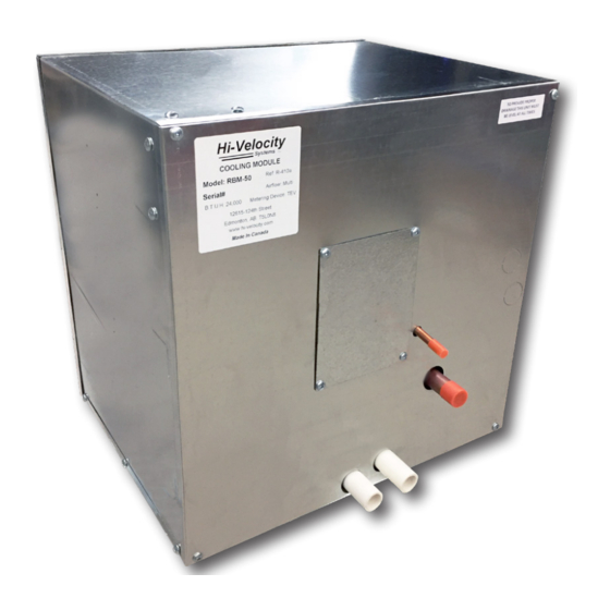
Hi-Velocity RBM-50 Installationshandbuch - Seite 4
Blättern Sie online oder laden Sie pdf Installationshandbuch für Kontrolleinheit Hi-Velocity RBM-50 herunter. Hi-Velocity RBM-50 12 Seiten. Rbm refrigerant base module

To change from up/right (standard) configuration to up/left configuration, follow the steps below.
1) Remove front door
from module. (Fig. 04)
2) Remove drain pan
by sliding it out from the
bottom. (Fig. 05)
3) Slide out the air
flow deflector plate. (Fig.
06)
4) Rotate entire unit 90
deg. clockwise. (Fig. 07)
www.hi-velocity.com
Change Configuration
Fig. 04
Fig. 05
Fig. 06
Fig. 07
-4-
-4-
RBM Refrigerant Base Module Installation
5) Slide the air flow
deflector
plate
back
into the section it was
removed from, in the new
orientation. (Fig. 08)
6) Replace the drain
pan
in
(new)
bottom
location. (Fig. 09)
7)
Remove
round
knock-outs on the door
to fit drain lines.
Plug
previously
used
drain
holes with provided plugs.
(Fig. 10)
8) Replace front door
on module. (Fig. 11)
Return Air
Knock-Out
Module RBM
Fig. 08
Fig. 09
Insert
Plugs
Remove
Knock-Outs
Fig. 10
Fig. 11
© 1995-2020 Energy Saving Products Ltd.
© 1995-2020 Energy Saving Products Ltd.
