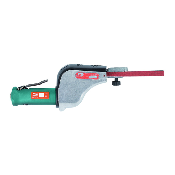
Dynabrade Dynafile 14000 Handbuch für Sicherheit, Betrieb und Wartung - Seite 6
Blättern Sie online oder laden Sie pdf Handbuch für Sicherheit, Betrieb und Wartung für Werkzeuge Dynabrade Dynafile 14000 herunter. Dynabrade Dynafile 14000 12 Seiten. 20,000 rpm / versatility kit
Auch für Dynabrade Dynafile 14000: Handbuch für Sicherheit, Betrieb und Wartung (12 seiten)

Disassembly/Assembly Instructions - Dynafile
16. Place 11418 Housing in a padded vise, slip 11424 Wave Spring, then 11419 Cover over the lock ring on the motor and install 01197 Motor to housing.
17. Tighten 95168 Screw with 9/64" allen wrench.
18. Install 11359 Tension Spring, 11421 Idler Arm Assembly, and 95216 Pivot Pin. Important: Use 1/8" diameter drive pin punch to line-up 11421 Idler Arm
Assembly with 11418 Housing.
19. Install 11419 Cover, contact arm assembly and abrasive belt.
Valve Body Assembly:
1. Insert 01247 Speed Regulator Assembly with o-rings into valve body. Secure with 95558 Retaining Ring.
2. Secure valve body in padded vise with air inlet point up.
3. Insert 01464 Seal into housing.
4. Line up hole in valve stem with hole in housing (looking past brass bushing). Insert 01472 Tip Valve so that the metal pin passes through the hole in the
valve stem. Install 01438 Spring (small end towards tip valve).
5. Install 53190 Block Plate along with 96065 O-Ring into housing.
6. Apply Loctite #567 PST Pipe Sealant to threads of 01494 Inlet Adapter and install into valve body (torque 23 N•m/200 in. - lbs.).
7. Install throttle lever and 01017 Pin.
Tool Assembly Complete. Please allow 30 minutes for adhesives to cure before operating tool.
Important: Motor should now be tested for proper operation at 90 PSIG. If motor does not operate properly or operates at a higher RPM than marked on
the tool, the tool should be serviced to correct the cause before use. Before operating, place 2-3 drops of Dynabrade Air Lube (P/N 95842) directly into air
inlet with throttle lever depressed. Operate tool for 30 seconds to determine if tool is operating properly and to allow lubricating oils to properly penetrate motor
Loctite
®
is a registered trademark of Loctite Corp.
Abrasive Belt Change and Removal:
To Remove Belt:
1. Open 11419 Cover.
2. Depress idler arm lever and pull belt away from the contact wheel.
3. Slip belt off drive wheel.
To Replace Belt:
1. Create a loop with belt by pinching together the sides of belt in the middle.
2. Slip one loop under the 01111 Drive Wheel and around the idler arm.
3. Depress idler arm lever and pull belt toward the contact wheel.
4. Slip belt over contact wheel.
5. Connect tool to power source.
6. Adjust belt tracking using 95218 Knob.
01089
Safety Throttle
Lever (Optional)
01247
Speed
Control
Screw
14000 Dynafile
11421
11011
Idler Arm
Idler Wheel
Assembly
Assembly
01197
11424
Air Motor
Wave
Spring
®
11420
Idler Arm
01111
11418
Drive
Housing
Wheel
Adjustment Knob
6
®
(continued)
11218
Contact
Arm Assembly
(See pages 8-11)
95218
Tracking
