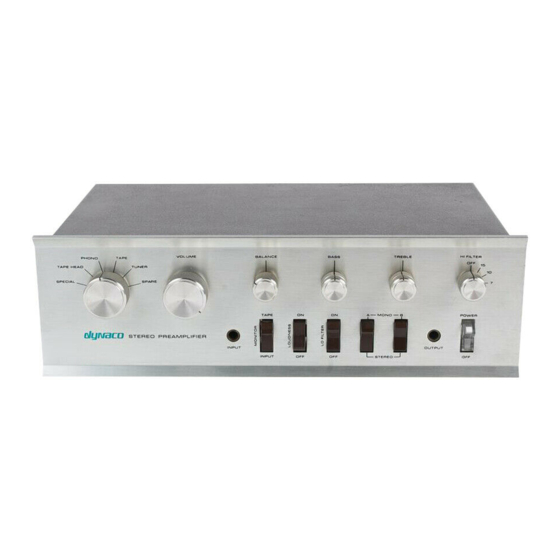
DYNACO PAT-4 Montageanleitung - Seite 7
Blättern Sie online oder laden Sie pdf Montageanleitung für Verstärken DYNACO PAT-4 herunter. DYNACO PAT-4 20 Seiten. Power supply
Auch für DYNACO PAT-4: Montageanleitung (16 seiten)

emitter of the transistor goes toward the bottom of the PCB (away from
the eyelets, see Figure 4).
d. Solder the three leads of the new transistor in place.
Figure 1-applying thermal compound and installing the heat sink
Page 7 of 20
