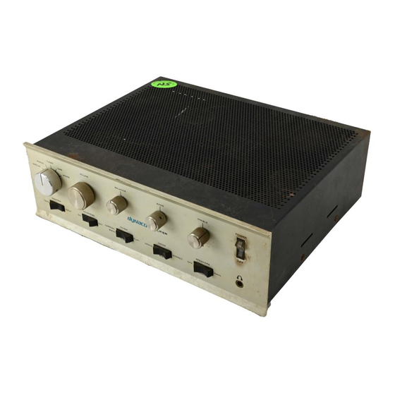
DYNACO SCA-80 Handbuch - Seite 2
Blättern Sie online oder laden Sie pdf Handbuch für Verstärken DYNACO SCA-80 herunter. DYNACO SCA-80 12 Seiten. C9 replacement
Auch für DYNACO SCA-80: Montageanleitung (15 seiten)

Table of Contents
Section 1: About This Manual ............................................................................................ 3
Who Should Attempt this Project? ................................................................................. 3
Tools You'll Need........................................................................................................... 3
Project Overview ............................................................................................................ 3
Important Safety Notes ................................................................................................... 4
Section 2: Preliminaries ...................................................................................................... 4
Opening the Amplifier .................................................................................................... 4
Check the Power Supply Voltage ................................................................................... 4
Removing C9 .............................................................................................................. 5
Building the Dynamite Capacitor ............................................................................... 5
Installing the New C9 into the Amplifier ....................................................................... 7
Check and Test Your Work .......................................................................................... 11
Reassemble the Amplifier ............................................................................................. 11
Results ........................................................................................................................... 11
References ..................................................................................................................... 11
Appendix 1 .................................................................................................................... 12
Wire Splicing Using Heat Shrink Tubing ................................................................. 12
Table of Figures
Figure 1-Side and Back views showing location of cover retaining screws....................... 4
Figure 2-Triple cap installed into the capacitor clamp ....................................................... 5
Figure 3-Ground Harness Configuration ............................................................................ 6
arrangement......................................................................................................................... 6
Figure 6-Reconnecting the wires to the new C9 ................................................................. 7
Figure 7-Stock amplifier layout (before C9 replacement) .................................................. 9
Figure 8-Stock Amplifier with Dynamite Capacitor Configuration Installed .................. 10
Page 2 of 12
