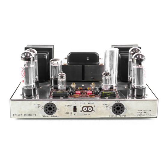
DYNACO Stereo 70 Handbuch zur Wiederherstellung - Seite 10
Blättern Sie online oder laden Sie pdf Handbuch zur Wiederherstellung für Verstärken DYNACO Stereo 70 herunter. DYNACO Stereo 70 20 Seiten. Series ii tube amplifier
Auch für DYNACO Stereo 70: Handbuch zur Wiederherstellung (5 seiten), Benutzerhandbuch (12 seiten), Anweisungen für die Montage (16 seiten)

Page 10
outlined in the documentation for the ASM-S7U-B module (available from
www.dynaco-doctor.com).
14. Finally install the original power and output transformers. Be certain to place the
left output transformer (the one with the longest red lead in the correct location).
B. Initial Wiring - Using Figure 2 as your guide, make the following connections (using
only 20 or 22 ga Teflon insulated wire):
15. Starting on the left channel, solder a loop of ¾' solid bare wire (you can use an
old component lead) from pin 1 to pin 8 of V3. Do the same for V2.
16. Next connect a 3" black wire from pin 8 of V3 to pin 1 of V2. Locate the 15.6
ohm power resistor originally removed from your amplifier and connect one end
to pin 8 of V3. Solder the other end of the 15.6 resistor to the ground lug near V2.
17. Finally connect a 4.5"black wire to pin 1 of V3. The other end will be connected
to pin 8 of the front panel left octal socket. Solder securely these four tube pins
(V3 pins 1 & 8 and V2 pins 1 & 8).
18. Next, connect a 3" black wire from pin 2 of V2 to pin 2 of V3. Next, connect a 7"
black wire to pin 2 of V3. Solder securely pin 2 of V3.
19. Next, connect a 3" black wire from pin 7 of V2 to pin 7 of V3. Next, connect a 7"
white wire to pin 7 of V3. Solder securely pin 7 of V3. Orient the 7" white wire
from this step and the 7" black wire from the previous step towards to front of the
amplifier and slightly twist together throughout their entire length. This pair will
eventually terminate on the new driver board and therefore should be oriented
towards the front inner edge of the amplifier.
20. Connect a 4" white wire to pin 5 of V3.
21. Connect a 4" white wire to pin 5 of V2.
22. Locate the left output transformer blue/white and green/white leads. Lightly twist
together and orient along the left outside edge of your amplifier. Trim to length
and connect the green/white lead to V2/pin4. Next connect the blue/white lead to
V2/pin3.
23. Locate the left output transformer blue and green leads. Lightly twist together and
orient along the left outside edge of your amplifier. Trim to length and connect
the green/white lead to V3/pin4. Next connect the blue/white lead to V3/pin3.
24. Locate the power transformer two green leads (these are quite heave gauge).
Lightly twist together and orient along the surface of the chassis towards the left
aiming at V2. Trim to length and connect one of the wires to V2/pin 7 and the
remaining green wire to V2/pin 2. You may want to orient these wires so that they
approach V2 from the left.
OK – the left channel output tube connections are completed. We will now perform
the same steps for the right channel:
25. Solder a loop of ¾' solid bare wire (you can use an old component lead) from pin
1 to pin 8 of V6. Do the same for V7.
Dynaco Stereo 70 Power Amplifier
Restoration Manual
Detailed Procedure & Guide
R0 4-03
10
