HiB 21700 Anleitungen zur Befestigung - Seite 2
Blättern Sie online oder laden Sie pdf Anleitungen zur Befestigung für Inneneinrichtung HiB 21700 herunter. HiB 21700 4 Seiten.
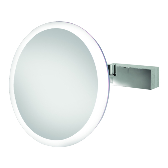
Installation
1. Position the magnifying mirror in a suitable location (according to the zonal diagram
overleaf, Figure 4), ensuring that the domestic electrical mains supply is within reach of the
electrical entry point of the product. Do not position in direct sunlight as the magnifying
effect of the mirror may pose a fire hazard.
2. Remove the wall bracket from the base of the mirror via the fixing(s) on the base of the unit
(see mounting diagram, figures 2).
3. Using the wall bracket as a guide, carefully mark the required drilling locations using a
soft pencil, ensuring it is level. Remove the wall bracket. Please ensure all marked drill
positions accurately match up with the fixing points of the wall bracket before drilling.
4. Using a suitable drill bit, drill holes in the marked positions to a suitable depth. If drilling
through tile, use a ceramic drill bit.
5. Insert wall plugs level with the surface of the wall. If fitting to a tiled surface, wall plugs
should be inserted below the tile surface to avoid cracking. NB. For plasterboard walls,
specialist fixings should be purchased, available from any DIY or hardware store.
6. Fix wall bracket into wall plugs.
7. Connect the domestic mains supply to the terminal box according to the wiring diagram
below (figure 1).
8. Place the mirror onto the wall bracket and secure into place using the fixing(s) on the mirror
base – take care not to trap wiring when assembling the mirror onto the wall bracket.
9. Switch on the domestic electrical mains supply to the mirror.
Operation Instructions
Cirque - To turn illumination on, press the touch switch on the underside of the mag mirror. To
colour temperature change, hold the switch to start the colour temperature cycle and release
when desired colour is displayed. To turn the illumination off, simply press the touch switch. The
colour temperature set will remain as the set colour.
Wiring Diagram (Fig. 1)
Earth is Green and Yellow
LUMINAIRE
2
Live is Brown
Neutral is Blue
Live supply can be Red or Brown
live
earth
Earth supply is Green and Yellow
neutral
Neutral supply can be Blue or Black
MAINS SUPPLY