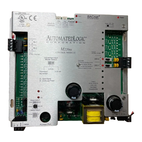
Automated Logic M220NX Technische Anweisungen - Seite 6
Blättern Sie online oder laden Sie pdf Technische Anweisungen für Kontrolleinheit Automated Logic M220NX herunter. Automated Logic M220NX 9 Seiten.

• 0 to 5VDC: The output impedance of a 0
to 5VDC source must not exceed
10kohms. The input impedance of the
M220nx is approximately 1Mohm.
• 0 to 20mA: The input resistance on the
"A" input is 250 Ohms. The "B" terminal
supplies a voltage source to power the
4-20mA transducer. The "B" terminal is
capable of supplying 18 to 24VDC, but
the total current of both "B" terminals
must not exceed 40mA. If the voltage
measured from the "B" terminal to Gnd
is less than 18VDC, you need to use an
additional external power supply.
• Dry Contact: A 5VDC wetting voltage is
used to detect contact position. This
results in a 0.5mA maximum sense
current when the contacts are closed.
Table 2. Input wiring restrictions
Maximum
Input
Length
0 to 5VDC
50 feet
15 meters
Thermistor
50 feet
Dry contact
15 meters
0 to 20mA
150 feet
46 meters
The M220nx accumulates up to ten input
pulses per second.
1. Be sure the M220nx's power is off before
wiring any inputs or outputs.
2. Connect the input wiring to the screw
terminals on the module as shown in
Figure 4.
NOTE If a 4-20 mA sensor uses an
external 24VAC power supply, connect
Revised 4/3/00 • M220nx
Minimum
Gauge
Shielding
24AWG
shielded and
grounded to
"
"
module's
B
or Gnd
terminal
24AWG
shielded and
grounded to
"
"
module's
B
or Gnd
terminal
20AWG
unshielded
PW R
0-5VDC
OUT
GND
DRY
CONTACT
PASSIVE
TRANSDUCER
4-20mA
12V or 24V
LOOP INPUT
THERMISTOR
OUT
3 WIRE
PW R
4-20mA
GND
OUT +
4 WIRE
OUT -
4-20mA
GND
PW R
ISOLATED AC
OUT +
or DC POWER
OUT -
SUPPLY
Figure 4. Input Wiring
one leg of the 24VAC supply to the module
ground.
3. Set the configuration jumper for each
input to indicate the type of input used.
Make sure the jumper is positioned
correctly, and be sure to grip the jumper
by the sides only. See Figure 5 on page 7.
4. For each input, enter the channel number,
offset, and gain on the Function Block's
Parameter page in SuperVision. Valid
channel numbers are listed in "Channel
Numbers" on page 7.
5. To verify each input's operation, have
each sensor create a known value and
6
© 2000 Automated Logic Corporation
Universal Input
Mode Select
Inputs
5V Max, 20mA Max
TO MODULE GND
