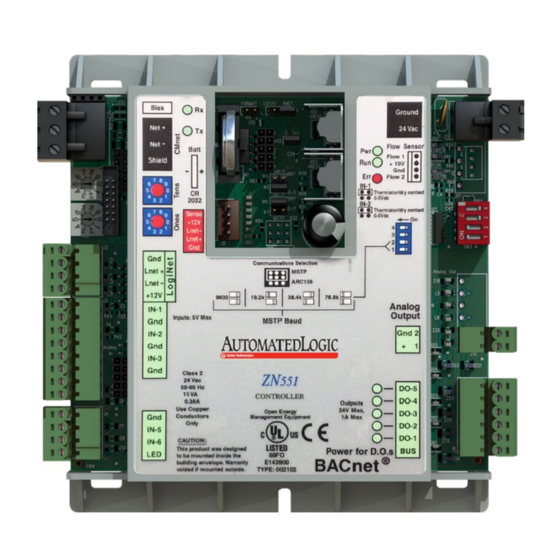
Automated Logic ZN551 Technische Anweisungen - Seite 3
Blättern Sie online oder laden Sie pdf Technische Anweisungen für Netzwerk-Router Automated Logic ZN551 herunter. Automated Logic ZN551 18 Seiten. Control module

Inputs
Room sensors
Digital outputs
Analog outputs
ZN551 Control Module • Rev. 3/17/2005
Status indicators
Environmental operating
range
Physical
Overall dimensions
Mounting dimensions
Weight
BACnet support
Listed by
The ZN551 has 5 inputs that accept the following signal types:
These
Support this
inputs...
signal type...
All
Thermistor
All
Dry contact
IN-1, IN-2
0–5 Vdc
IN-4, IN-5
LogiStat
NOTE A LogiStat sensor connected to the ZN551 uses IN-4 and IN-5. An RS
room sensor connected to the Rnet port does not use these inputs.
You can wire an RS Standard, RS Plus or RS Pro to the ZN551's Rnet port.
Or you can wire a LogiStat or LogiStat Plus to the ZN551's LStat port. See the
RS Room Sensors Technical Instructions (http://info.automatedlogic.com) or
the LogiStat Sensors Technical Instructions (http://info.automatedlogic.com).
NOTE The ZN551 does not support the LogiStat Pro.
The ZN551 has 5 digital outputs. You can connect each output to a
maximum of 24 Vac/Vdc. Each output is a dry contact rated at 1 A, 24 V
maximum and is normally open.
The ZN551 has 1 analog output that supports voltage devices from 0-10 Vdc.
The controlled device must have a minimum of 2000 Ohms resistance
3
LED's indicate status of communications, running, errors,
power, and digital outputs
0 to 130°F (-17.8 to 54.4°C), 10–90% relative humidity,
non-condensing
Rugged GE C2950 Cycoloy plastic
Width:
5 1/16 in. (12.9 cm)
Height:
5 11/16 in. (14.4 cm)
5 9/16" (14.1 cm) between mounting slot centerlines
0.6 lbs (0.27 kg)
Conforms to the Advanced Application Controller (B-AAC)
Standard Device Profile as defined in ANSI/ASHRAE
Standard 135-2004 (BACnet) Annex L
UL-916 (PAZX), cUL-916 (PAZX7), FCC Part 15-Subpart B-
Class A, CE EN50082-1997
Description
Precon type 2 (10 kOhm at 77°F). Input voltages will be
from 0.33 Vdc to 2.52 Vdc for thermistors.
A 3.3 Vdc wetting voltage detects contact position,
resulting in a 0.3 mA maximum sense current when the
contacts are closed.
The output impedance of a 0–5 Vdc source must not
exceed 100 Ohms. The input impedance of the ZN551
is approximately 30 kOhm.
IN-4–See Thermistor.
IN-5–Setpoint adjust. Input voltages should be from
1.4–3.4 Vdc.
© 2005 Automated Logic Corporation
