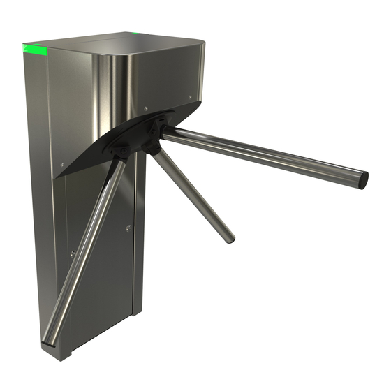
Automatic Systems TriLane TL1 Schnellstart-Handbuch - Seite 5
Blättern Sie online oder laden Sie pdf Schnellstart-Handbuch für Drehkreuze Automatic Systems TriLane TL1 herunter. Automatic Systems TriLane TL1 11 Seiten. Tripod turnstile

p. 5/11
4.6. IN THE EVENT OF POWER FAILURE
Depending on the type of mechanics installed inside the unit, the TriLane tripod turnstile can either release or not
release passage if power to the equipment is lost. This unlocking principle in the case of an emergency situation
is referred to as "anti-panic". The dropped arm has to be manually place back to the horizontal position by a turret
rotation. On the motorized version, a turret rotation is automatically performed at power on.
5. INSTALLATION
5.1. RECOMMENDED TOOLS
5.2. PRELIMINARY WORK
• The turnstile has been specially packaged for transport. Bring the material to the installation site with the help of
a forklift truck and remove the packing material.
• Remove the top cover (two screws M6, see attached picture) to access the mechanism, the motor control board
(optional) and the functional pictograms.
• Open the front panel with the two keys to get access to the main control board, the main switch and to fixing points
on the floor.
• Check the condition of the material - although it has been carefully packed, damage may have occurred during
transport.
The information contained in this document is the property of Automatic Systems and is confidential. The recipient shall refrain from using this information for any purpose
other than the use of the products or the execution of the project to which it refers and from communicating it to third parties without prior written agreement of Automatic
Systems. The document is subject to change without notice.
4:24
4:23
•
Standard electrical tools.
•
Flat spanner set.
•
Set of Allen keys.
•
Spirit level.
•
Hammer drill + concrete drill bit - Ø 15 x 100
•
Standard protective equipment: gloves, goggles, hard hat and safety shoes.
2x fixing screw M6 to
unlock the cover
2x locks with identical
key to remove the front
panel
Ref.:
04:23 Support for electronic devices
04:24 Control logic board AS1635
Fig. 3 - Electrical card, left
Fig. 4 - Removing the cover.
TL1-QSG-EN-02
Designation:
