GAI-Tronics 351-001 Benutzerhandbuch - Seite 11
Blättern Sie online oder laden Sie pdf Benutzerhandbuch für Telefon GAI-Tronics 351-001 herunter. GAI-Tronics 351-001 16 Seiten. Div. 2 industrial telephones
M
226-002, 341-001,
ODEL
Model 351-001
Mounting and wiring of the Model 351-001 must be in accordance with Div. 2 installation standard
practices.
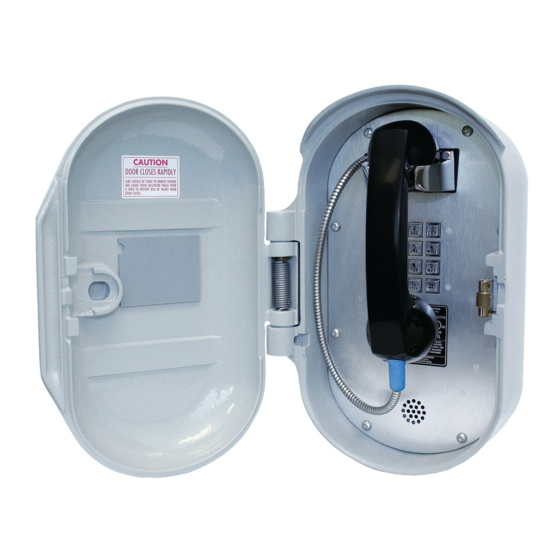
1. Open the front door of the enclosure. Locate the four outermost screws.
2. Remove the four outermost screws, and carefully pull the enclosure apart until encountering a slight
resistance on the left side.
3. Open the front half of the enclosure to the left.
4. Pull on the left side of the enclosure until the hinge plugs pull loose to separate the front half from the
rear half. Set the front half of the enclosure aside.
5. Mount the enclosure on the wall using four 1/4-20 machine screws with nuts and washers or #14
wood screws of appropriate length, depending on the mounting surface.
6. Enter the rear enclosure with telephone wiring per accepted Div. 2 standards.
7. Insert the front half of the telephone hinges into the rear enclosure, remaining open to the left.
8. Connect the telephone cord's modular connector to the incoming subscriber line using the appropriate
mating connector or connect the incoming line directly to the terminal strip per Figure 6
e:\standard ioms - current release\42004 instr. manuals\42004-339f.doc
07/14
351-001 D
. 2 I
AND
IV
NDUSTRIAL
Figure 8. Model 351-001 Outline Drawing
T
ELEPHONES
P
. 42004-339F
UB
10 of 14
P
AGE