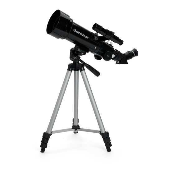
Celestron 21038 Travel Scope 50 Gebrauchsanweisung - Seite 6
Blättern Sie online oder laden Sie pdf Gebrauchsanweisung für Teleskop Celestron 21038 Travel Scope 50 herunter. Celestron 21038 Travel Scope 50 18 Seiten. Travel scope

Attaching the Telescope O pti cal Tube to the Tri pod
Attaching the Telescope O pti cal Tube to the Tri pod
The telescope optical tube attaches to the tripod by using the mounting bracket on the bottom of the optical tube
(Figure 2-7 shows the Travel Scope 70; and the Travel Scope 50 is similar) and the mounting platform of the tripod
(Figure 2-8). Before starting make sure all of the knobs on the tripod are locked.
1.
Remove the protective paper covering the optical tube.
2.
Loosen the top right knob (see Figure 2-8) by turning it counterclockwise. This allows you to tilt the tripod
platform up 90° as shown in Figure 2-9. After tilting the platform up, tighten the knob to secure it in place.
3.
Figure 2-10 shows the bottom of the optical tube and the tripod platform and where they will attach to each
other.
4.
Under the center of the tripod platform you will see (Figure 2-10) a knob which contains a ¼ x 20 screw
that will attach securely the platform to the telescope optical tube.
5.
You can put the ¼ x 20 screw into either of the threaded holes of the Travel Scope 70 (it doesn't matter
which one you use) in the mounting bracket of the telescope optical tube whereas the Travel Scope 50 has
only one threaded hole. Hold the optical tube with one hand while threading the screw clockwise until tight
with the other hand. Now the assembly will look like Figure 2-11.
6.
Lastly, loosen the knob for the tripod platform and lower the platform down to the level position and then
tighten the knob securely.
Figure 2-9
Movi ng the Travel Scope Manually
Movi ng the Travel Scope
The Travel Scope is easy to move wherever you want to point it. The up and down (altitude) is controlled by the
Pan Handle (Figure 1-1) Control Knob. The side-to-side (azimuth) is controlled by the Azimuth Locking Knob (top
left knob in Figure 2-8). Both knobs are loosened when turned counterclockwise and tightened when turned
clockwise. When both knobs are loose you can find your objects easily (through the Finderscope which is discussed
shortly) and then lock the controls.
Figure 2-7
Figure 2-10
Manually
6
Figure 2-8
Figure 2-11
