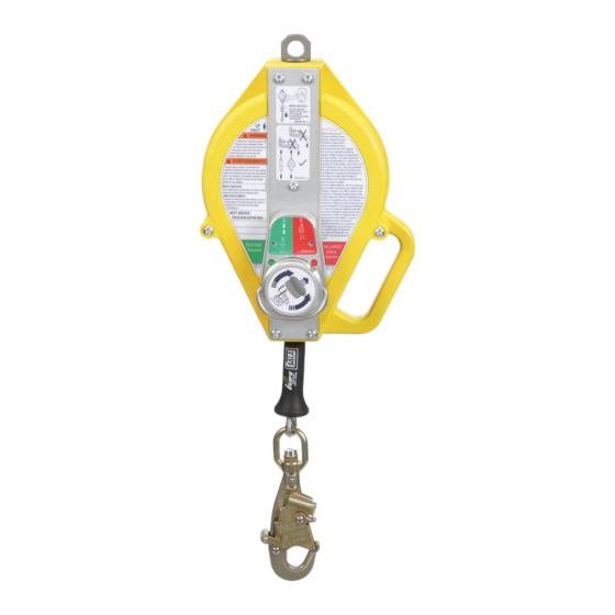
DBI SALA ULTRA-LOK 3501104 Gebrauchsanweisung - Seite 7
Blättern Sie online oder laden Sie pdf Gebrauchsanweisung für Sicherheitsausrüstung DBI SALA ULTRA-LOK 3501104 herunter. DBI SALA ULTRA-LOK 3501104 16 Seiten. Self-retracting devices

4.0 OPERATION
WARNING: Do not alter or intentionally misuse this equipment. Consult Capital Safety when using this
equipment in combination with components or subsystems other than those described in this manual. Some
subsystem and component combinations may interfere with the operation of this equipment. Use caution when
using this equipment around moving machinery, electrical hazards, chemical hazards, sharp edges, or overhead
materials that may fall onto the lifeline. Do not loop the lifeline around small structural members. Failure to heed
this warning may result in equipment malfunction, serious injury, or death.
WARNING: Consult your doctor if there is reason to doubt your fi tness to safely absorb the shock from a fall
arrest. Age and fi tness seriously affect a worker's ability to withstand falls. Pregnant women or minors must not
use DBI-SALA Self-Retracting Lanyards.
4.1
BEFORE EACH USE: Before each use of this fall protection equipment carefully inspect it to assure it is in
good working condition. Check for worn or damaged parts. Ensure all bolts are present and secure. Check
that the lifeline is retracting properly by pulling out the line and allowing it to slowly retract. If there is any
hesitation in retraction the unit should be marked as "UNUSABLE" and returned to an authorized service center
for service. Inspect the lifeline for cuts, frays, burns, crushing and corrosion. Check locking action by pulling
sharply on the line. See Section 5 for inspection details. Do not use if inspection reveals an unsafe condition.
4.2
AFTER A FALL: Any equipment which has been subjected to the forces of arresting a fall or exhibits
damage consistent with the effect of fall arrest forces as described in Section 5, must be removed from
service immediately, marked as "UNUSABLE", and inspected and serviced as instructed in Sections 5 and 6.
Figure 8 – Tripod Mounting
7
1
3
2
