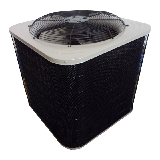
Aire-Flo 59 Installationsanleitung Handbuch - Seite 3
Blättern Sie online oder laden Sie pdf Installationsanleitung Handbuch für Klimagerät Aire-Flo 59 herunter. Aire-Flo 59 18 Seiten. 14 seer

WARNING
When using a high pressure gas such as
nitrogen to pressurize a refrigeration or air
conditioning system, use a regulator that
can control the pressure down to 1 or 2 psig
(6.9 to 13.8 kPa).
WARNING
Polyol ester (POE) oils used with HFC-410A
refrigerant absorb moisture very quickly. It is very
important that the refrigerant system be kept closed
as much as possible. DO NOT remove line set caps
or service valve stub caps until you are ready to make
connections.
IMPORTANT !
Some scroll compressors have an internal vacuum
protector that will unload scrolls when suction pres
sure goes below 20 psig. A hissing sound will be
heard when the compressor is running unloaded.
The protector will reset when low pressure rises
above 40 psig. DO NOT REPLACE COMPRESSOR.
LIQUID LINE FILTER DRIER INSTALLATION
The provided filter drier must be field installed in the liquid
line between the outdoor unit's liquid line service valve and
the indoor coil's metering device (fixed orifice or TXV) as
illustrated in figure 4. This filter drier must be installed to
ensure a clean, moisture-free system.
Typical Liquid Line Filter Drier Installation
LIQUID LINE
LINE
SERVICE VALVE
OUTDOOR
UNIT
BRAZE CONNECTION POINTS
LIQUID LINE
FILTER DRIER
FIGURE 4
Refrigerant can be harmful if it is inhaled. Refrigerant
must be used and recovered responsibly.
Failure to follow this warning may result in personal injury
or death.
TABLE 1. REFRIGERANT LINE SET — INCHES
MODEL
18
24
30
36
41
42
47
48
59
60
LIQUID
LINE
Page 3
WARNING
14 SEER
LIQUID
SUCTION
LINE
3/8
3/8
3/8
3/8
3/8
3/8
3/8
3/8
3/8
3/8
LINE
3/4
3/4
3/4
7/8
7/8
7/8
7/8
7/8
1-1/8
1-1/8
