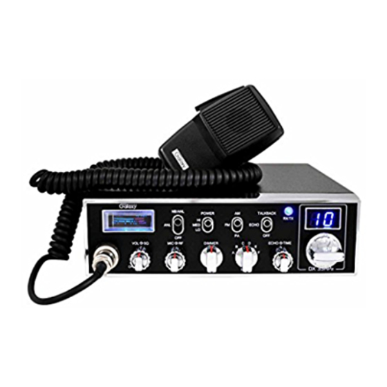
Galaxy DX−33HML Benutzerhandbuch - Seite 4
Blättern Sie online oder laden Sie pdf Benutzerhandbuch für Sende- und Empfangsgerät Galaxy DX−33HML herunter. Galaxy DX−33HML 8 Seiten. Full channel am/fm mobile transceiver

RECEIVER
Sensitivity
Selectivity
Image Rejection
IF Frequency
Adjacent-Channel
Rejection
RF Gain Control
Automatic Gain Control
(AGC)
Squelch
ANL
Noise Blanker
Audio Output Power
Frequency Response
Built-in Speaker
External Speaker (Not
Supplied)
AM: 0.5 µV for 10 dB (S+N)/N at greater than
½ -watt of audio output.
FM: 1.0 µV for 20 dB (S+N)/N at greater than
½-watt of audio output.
AM/FM: 6 dB @ 3 KHz, 50 dB @ 9 KHz.
More than 65 dB.
st
AM/FM: 10.695 MHz 1
IF, 455 KHz 2
60 dB AM
45
dB
adjustable
for
optimum
reception.
Less than 10 dB change in audio output for
inputs from 10 to 100,000 microvolts.
Adjustable; threshold less than 0.5 µV.
Switchable
RF type
4 watts into 8 ohms.
300 to 2800 Hz.
8 ohms, round.
8 ohms; disables internal speaker when
connected.
- 3 -
ATERNATE MICROPHONES AND INSTALLATION
For best results, the user should select a low-impedance dynamic type
microphone or a transistorized microphone. Transistorized type microphones have
a low output impedance characteristic. The microphones must be provided with a
four-lead cable. The audio conductor and its shielded lead comprise two of the
leads. The fourth lead is for receive control, and the third is for transmit control.
The microphone should provide the functions shown in schematic below.
nd
IF
signal
If the microphone to be used is provided with pre-cut leads, they must be revised as
follows.
1. Cut leads so that they extend 7/16" beyond the plastic insulating jacket of the
microphone cable.
2. All leads should be cut to the same length. Strip the ends of each wire 1/8" and
tin the exposed wire.
Before beginning the actual wiring read carefully, the circuit and
wiring information provided with the microphone you select. Use the
minimum head required in soldering the connections. Keep the exposed
wire lengths to a minimum to avoid shorting when the microphone plug is
reassembled.
4 WIRE MIC CABLE
Pin Number
Mic Cable Lead
1
Audio shield
2
Audio Lead
3
Transmit control
4
Receive Control
Fig. 1 Your transceiver microphone schematic.
- 12 -
