Autonics TX Series Produkthandbuch
Blättern Sie online oder laden Sie pdf Produkthandbuch für Temperaturregler Autonics TX Series herunter. Autonics TX Series 6 Seiten. Lcd pid temperature controllers
TCD220019AA
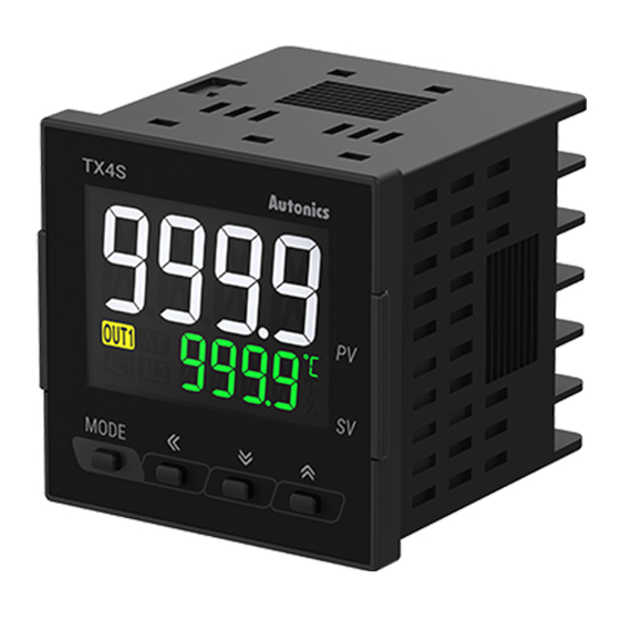
LCD PID Temperature
Controllers
TX Series
PRODUCT MANUAL
For your safety, read and follow the considerations written in the instruction
manual, other manuals and Autonics website.
The specifications, dimensions, etc are subject to change without notice for product
improvement Some models may be discontinued without notice.
Features
• 50ms high-speed sampling rate and ±0.3% display accuracy
• Large LCD display with easy-to-read white PV characters
• Switch between current output and SSR drive output
• SSR drive output (SSRP function) control options : ON/OFF control, cycle control,
phase control
• Communication output model available : RS485 (Modbus RTU)
• Parameter configuration via PC (RS485 communication) : DAQMaster software
included (comprehensive device management software)
• Compact, space-saving design with 45 mm depth : 30% rear-length size reduction
compared to similar-sized (48×48 mm) models from Autonics
Terminal protection cover sold separately : RSA-COVER
* Korea Patent Registration 30-2020-0020300, Korea Patent Registration 10-1651262, U.S.A. Patent Registration
10281339, Japan Patent Registration 6603317, China Patent Registration ZL201580039398.2, Germany Patent
Application 112015003239.8
*Korea Design Registration 30-0999138
ᜢ ᜧ ᜫ
Safety Considerations
• Observe all 'Safety Considerations' for safe and proper operation to avoid hazards.
• symbol indicates caution due to special circumstances in which hazards may occur.
Warning
Failure to follow instructions may result in serious injury or death
01. Fail-safe device must be installed when using the unit with machinery that
may cause serious injury or substantial economic loss.(e.g. nuclear power
control, medical equipment, ships, vehicles, railways, aircraft, combustion
apparatus, safety equipment, crime/disaster prevention devices, etc.)
Failure to follow this instruction may result in personal injury, economic loss or fire.
02. Do not use the unit in the place where flammable/explosive/corrosive gas,
high humidity, direct sunlight, radiant heat, vibration, impact or salinity
may be present.
Failure to follow this instruction may result in explosion or fire.
03. Install on a device panel to use.
Failure to follow this instruction may result in fire or electric shock.
04. Do not connect, repair, or inspect the unit while connected to a power
source.
Failure to follow this instruction may result in fire or electric shock.
05. Check 'Connections' before wiring.
Failure to follow this instruction may result in fire.
06. Do not disassemble or modify the unit.
Failure to follow this instruction may result in fire or electric shock.
Caution
Failure to follow instructions may result in injury or product damage
01. When connecting the power input and relay output, use AWG 20 (0.50 mm
cable or over, and tighten the terminal screw with a tightening torque of 0.74
to 0.90 N m.
When connecting the sensor input and communication cable without
dedicated cable, use AWG 28 to 16 cable and tighten the terminal screw with
a tightening torque of 0.74 to 0.90 N m.
Failure to follow this instruction may result in fire or malfunction due to contact
failure.
02. Use the unit within the rated specifications.
Failure to follow this instruction may result in fire or product damage
03. Use a dry cloth to clean the unit, and do not use water or organic solvent.
Failure to follow this instruction may result in fire or electric shock.
04. Keep the product away from metal chip, dust, and wire residue which flow
into the unit.
Failure to follow this instruction may result in fire or product damage.
Cautions during Use
• Follow instructions in 'Cautions during Use' . Otherwise, it may cause unexpected
accidents.
• Check the polarity of the terminals before wiring the temperature sensor. For RTD
temperature sensor, wire it as 3-wire type, using cables in same thickness and length.
For thermocouple (TC) temperature sensor, use the designated compensation wire for
extending wire.
• Keep away from high voltage lines or power lines to prevent inductive noise. In case
installing power line and input signal line closely, use line filter or varistor at power line
and shielded wire at input signal line. Do not use near the equipment which generates
strong magnetic force or high frequency noise.
)
2