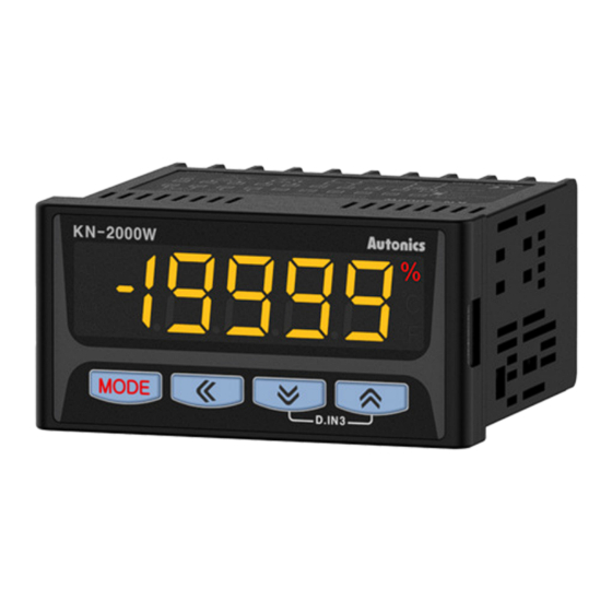
Autonics KN-2000W Series Produkthandbuch - Seite 3
Blättern Sie online oder laden Sie pdf Produkthandbuch für Messgeräte Autonics KN-2000W Series herunter. Autonics KN-2000W Series 6 Seiten. 1-channel digital temperature indicators

Dimensions
• Unit: mm, For the detailed drawings, follow the Autonics website.
96
■ Panel cut-out
≥ 116
92
Connections
■ KN-20□□W
RTD/TC/mV/±1V
-1to+10V
0to20mA
■ KN-22□□W
10
3
90
■ Bracket
96
+0.6
0
F.G.
■ KN-24□□W
Errors
Display
Description
Flashes when input sensor is disconnected or
sensor is not connected.
BURN
Flashes when PV is higher than input range.
HHHH
Flashes when PV is lower than input range.
LLLL
Flashes when there is an error of setting value
ERR
Flashes when parameter and selection switch
setting for input specification are inconsistent
ERR1
Mode Setting
→ Monitoring mode setting
[MODE]
→
RUN
[MODE] over 3 sec
→
[▲] + [▼] over 3 sec
Supply the power with pressing
→
[M]+ [◀]
Parameter Setting
• Some parameters are activated/deactivated depending on the model or setting of
other parameters. Refer to the descriptions of each item.
• [MODE] key: Move to next item after saving / Return to RUN mode after saving (≥ 3
sec)
• [◀] key: Select parameter / Move digits
• [▲], [▼] key: Select parameter / Change setting value
• Return to the upper level without saving when there is no key input for more than 30
seconds.
■ Monitoring mode
Parameter
Display Default Setting range
AL1 alarm
1-1
temperature
AL1
09(9
AL2 alarm
1-2
temperature
AL2
09(9
AL3 alarm
1-3
temperature
AL3
00)1
AL4 alarm
1-4
temperature
AL4
00)1
High peak
1-5
display
hPEK
----
Low peak
1-6
display
lPEK
----
Troubleshooting
Check input sensor status.
When input is within the
rated input range, this display
disappears.
Check the setting condition and
reset.
Check input specification.
[MODE] over 3
sec
Program mode setting
Digital input
Auto
Parameter reset
Auto
Within input range
Analog Input: L-SC ≤ AL□ ≤ H-SC
[4 alarm output model]
Same as 1-1/2 AL1/2 alarm temperature
Check only (not available to set)
Displays high/low peak (Max./Min.
input) value
• Initial high/low peak is saved after 2
sec from supplying the power.
• Value reset: [▲] + [▼] key over 3
sec in 1-5/6 High/Low peak display
parameter
→
RUN
→
→
Condition
2-12/14/16/18
AL-1/2/3/4
alarm
operation: AT1,
AT2
-
