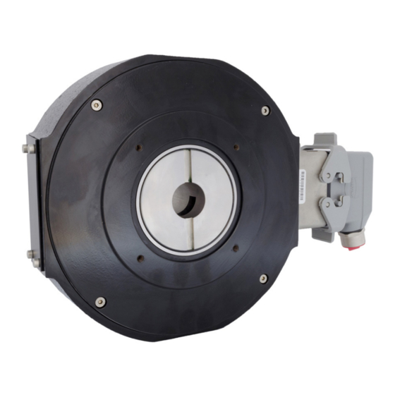
DYNAPAR NorthStar NexGen RIM Tach HT85 Installationshandbuch - Seite 5
Blättern Sie online oder laden Sie pdf Installationshandbuch für Medienkonverter DYNAPAR NorthStar NexGen RIM Tach HT85 herunter. DYNAPAR NorthStar NexGen RIM Tach HT85 7 Seiten.

Figure 3: Anti-Rotation Arm Orientation
7. Position anti-rotation arm at a 90° angle to the
motor shaft (perpendicular to motor axis and motor
C-face is recommended). This orientation ensures
three things:
• It provides enough clearance between the HT85
encoder and point of attachment (weldment angle or
channel bracket, motor face or foot, or other stable
mounting)
• It gives long moment arm from encoder centerline,
thus minimizing housing rotation and encoder error
caused by relative rotation
• It reduces misalignment of bearing rod ends which
prevents binding and premature wear due to high
degrees of angular misalignment
8. Loosely adjust anti-rotation arm to desired length.
Apply thread locker on threaded rod where bearing
rods will rest. The free end of the anti-rotation arm
should then be mounted to a stationary surface such
as a welded channel, angle, motor flange, or foot.
Tighten locking nuts (using a 9/16" open wrench)
against bearing rod ends and mounting stud.
IMPORTANT: Do not disrupt the anti-rotation
arm's 90° alignment with the motor shaft during
mounting. A parallel orientation between
the anti-rotation arm and motor shaft is not
recommended because it will significantly
reduce the anti-rotation arm's performance and
operational lifetime. Each rod end can withstand
only 50 of deviation. Ideally, the anti-rotation
arm should be mounted with rod-end ball
centered in its socket. Recommended torque: 20
ft-lbs. [27 N-m].
1.1 SENSOR MODULE INSTALLATION
To install the Sensor Module, perform the following
steps. See Figure 4.
1. Remove sensor module and mating connector
from packaging.
2. Separate mating connector from sensor module
by releasing the two latches.
3. Insert sensor module into opening in enclosure.
The sensor assembly is keyed to ensure proper
orientation.
4. Locate four M4-0.7 socket head screws. Insert the
screws through clearance holes in sensor module
and into tapped holes in enclosure. Tighten to a
nominal 15 in-lbs [1.7 N-m regular].
NOTE: There should not be a gap between the lip
on the housing and the enclosure. The stainless
steel sensor module is designed to seat in metal
to metal contact with the enclosure. Ensure that
no gaskets, paint, dirt, etc., interferes with the
complete seating of the module in the enclosure.
Figure 4: Sensor Module Installation
Page 5
