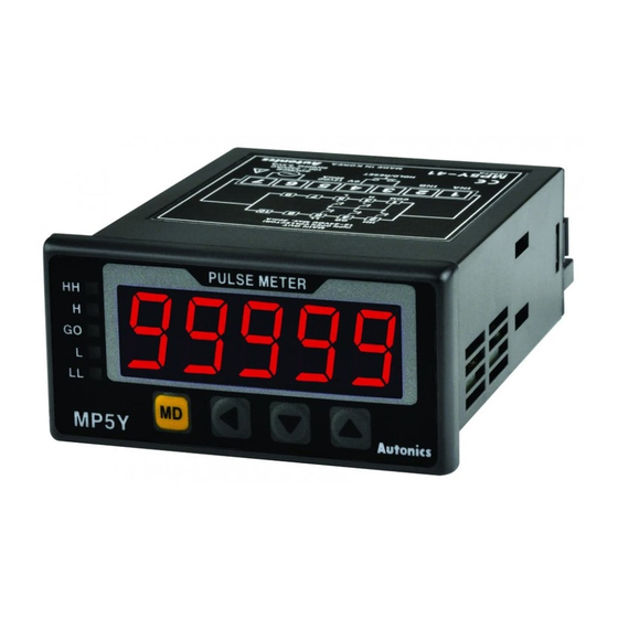
Autonics MP5W Series Gebrauchsanweisung - Seite 7
Blättern Sie online oder laden Sie pdf Gebrauchsanweisung für Messgeräte Autonics MP5W Series herunter. Autonics MP5W Series 8 Seiten. Multi pulse meters

■ F13: accumulation
Measures and displays the counted value of input A pulses.
Accumulation = P × α
Display value Display unit
Accumulation Quantity [EA]
• Operation
① Counts the number of input A pulses.
② Input B is an enable input signal. During ON, the quantity and display value of input A
will be held, and during OFF input A will be recounted.
③ When RESET input is ON, the integrated counted value will be reset to "0"
Input A
1
2
3
4
5
6
Input B
RESET
Display
0
1
2
3
4
5
6
• α = display value for 1
■ F14: addition / subtraction-individual input
Displays the counted value from added input A pulses and subtracted input B
pulses. When there are two inputs simultaneously, it will not count.
Add / Sub
= input A × α - input B × α
(individual)
Display value
Display unit
Addition /
Subtraction
Quantity [EA]
(individual)
Input A
Input B
RESET
Display 0
1
2
3
2
0
1
• α = display value for 1
■ F15: addition / subtraction-phase difference input
When input A is Low, counting is added to the low of input B.
When input A is Low, counting is subtracted from the high of input B.
= Detects position and speed
Add / Sub
using A and B phases of
(phase difference)
encoder outputs as input.
Display value
Display unit
Addition /
Subtraction
Quantity [EA]
(phase difference)
Input A
Input B
RESET
0
1
2
3
2
1
0
Display
■ F16: length measurement 2
Measures and displays the number of pulses from input A until the value of input B
reaches the setting value.
Length
= P × α
measurement
(until the setting value of
2
input B)
Display value
Display unit
Length
Quantity [EA]
measurement 2
• If input A and input B are ON during initial power supply, it will not count and only count the
number of rising edge.
• Display value is renewed depending on the P2-13. Display cycle.
(e.g.: input B = 4)
Input A
1
2
1
2
Input B
RESET
Display
0
1
2
3
4
0
1
2
3
4
0
Display
01)
01) When P2-13 Display cycle is OFF, it will maintain the quantity of input A until the value
of input B reaches the setting value of P2-14 Input B setting value (INB).
• P: number of input A pulses
• α: prescale value
1
2
3
4
0
1
2
3
4
• α: prescale value of input A
MP5
Photoelectric
Input B
sensor
Input A
(sub)
(add)
2
3
2
1
Input A
Input B
MP5
1
2
0
• P: number of input A pulses
• α: prescale value
3
4
2
3
1
5
6 7
0
1
2
3
4 5
7
Functions
■ Hysteresis
Near the comparative setting value, the output may turn ON / OFF frequently and
unstably. To prevent this, hysteresis value is set based on the comparative setting value.
MP5
Comparative
value H, HH
Comparative
value L, LL
Output H, HH
Output L, LL
■ Delay monitoring: limit comparative output
After supplying power, the starting current of motors and other inputs are changeable.
This function allows stable control by limiting all outputs for a certain period of time,
until the target measurement unit stabilizes. It may also control L,LL outputs until a
specific output is reached.
• After supplying power, there is no initial L, LL comparative outputs.
• Each setting value of HH, H, LL, L is not related to their relative sizes.
• E.g.: S (Standard) output mode
HH
H
L
LL
HH
H
GO
L
LL
Comparative output limit
function removal
■ Delay monitoring:
Start compensation timer
Set monitoring delay time so that there is
no output during the delay time.
■ Auto-zero time
When there is no input signal during auto-zero setting time, the display value is
automatically set to 0(zero). Please set the auto-zero setting time so that it is longer
than the interval of the slowest input signal. If the setting time is too long and there is
no input signal, the rate at which the display value falls to 0(zero) decrease, and output
response rate may slow down.
■ Data bank
Comparative setting value and prescale value are saved as two types(data bank 1, 2)
and can be selected for use by opening or shorting of terminals.
• Terminal 3, 5 open: use value of data bank 1
• Terminal 3, 5 short: use value of data bank 2
■ Prescale
Displays values in required units or specific multiples by counting the number of input
pulses, then multiplying the number of pulses or the length of pulses by variables
(X×10y).
• E.g.: prescale value (α = 15) setting
• f: the number of input pulses per
second [Hz]
• α: prescale value
• N: the number of pulses per revolution
Set mantissa(X) as 1.5000, and exponent(Y) as 1 for prescale value(α)=15.
The same display value can be obtained with α value set as X=0.1500, and Y=2
• A: hysteresis
• The hysteresis value can be set to "0" but
the actual operation value is "1"
A
A
• E.g.: F (Deflection) output mode
The comparative output limiting function is
removed at the set value (standard setting).
Comparative output limit
(Max.)H deviation
SV
(Min.) L deviation
L, LL
Comparative
value
Output
Revolutions
= f × α
(rpm)
= f × 60 × (1 / N)
= f × 60 × (1 / 4)
MP5
= f × 60 × 0.25
= f × 15
function removal
H
L
Delay monitoring time
No output
