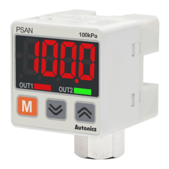
Autonics PSAN Series Produkthandbuch - Seite 5
Blättern Sie online oder laden Sie pdf Produkthandbuch für Messgeräte Autonics PSAN Series herunter. Autonics PSAN Series 7 Seiten. Display type pressure sensors
Auch für Autonics PSAN Series: Handbuch (2 seiten), Produkthandbuch (6 seiten), Handbuch (13 seiten)

Auto shift Preset Setting
■ Setting method
[Parameter setting]
1. Select P-9 External input terminall: SHFT.
2. Press the [▲] key for over 3 sec. in RUN mode to enter Max / Min monitoring / Auto
shift menu.
3. Press the [M] key to entering Auto shift setting and press the [▼] or [▲] key to
change preset.
4. When reset the set correctiong value, press the [▼] + [▲] keys for over 1 sec .
[External input setting]
1. At the desired preset value pressure, maintain low level for over 1 ms of Auto shift
input (orange).
2. The pressure at this time is measured and applied after 7.5 ms and is stored in the
auto shift correction value.
Operation
Preset
Default Setting range
mode
Auto-
SHFT Auto-shift ShIN
shift
■ Precaution
• Auto shift correction is reset as 0 when changing P-2
value.
• Preset setting range is wider than the rated pressure with the source pressure
fluctuations.
• In case of forced output control mode or PV HHHH/LLLL, Auto shift function does not
operate.
Error
Display Cause
When external pressure is input while
adjusting zero point.
ERR1
When overload is applied on control output
ERR2
When 'ST1', 'ST2' setting range is not met in
auto sensitivity setting mode.
ERR3
When applied pressure exceeds high-limit of
display pressure range.
HHHH
When applied pressure exceeds low-limit of
display pressure range.
LLLL
-HH-
Auto shift correction error.
-LL-
-HL-
Min. preset setting< SH.IN ≤ Max. preset setting
Setting range
Setting range
Pressure
(after correction)
(preset range)
Negavive
-101.3 to 5.0 kPa
-101.3 to 101.3 kPa
0
-5.0 to 110.0 kPa
-110.0 to 110.0 kPa
Static
-50.0 to 1100 kPa
-1100 to 1100 kPa
Compound -101.3 to 110.0 kPa -101.3 to 110.0 kPa
OUT operation mode and preset
Troubleshooting
Try again after removing external
pressure.
Remove overload.
Check setting conditions and set
proper setting values.
Apply pressure within display pressure
range.
Set the corrected setting value within
setting pressure range.
Sold Separately: Front Cover, Panel Bracket
• Unit: mm, For the detailed drawings, follow the Autonics website.
■ Front cover: PSO-P01
40
5.7
9.7
1
Installation configuration
• Panel thickness: 0.8 to 3.5 mm
Front cover (PSO-P01)
Panel bracket (PSO-B02)
Installation panel
Sold Separately: M5 gender
• Unit: mm, For the detailed drawings, follow the Autonics website.
■ PSO-Z01 (pneumatic type)
M5
PT1/8,
1.6
NPT1/8
8.1
■ Panel bracket: PSO-B02 / B03
30
3
40
• Panel cut-out
+0.5
□36
0
Panel thickness: 0.8 to 3.5 mm
Pressure sensor
20
25.8
