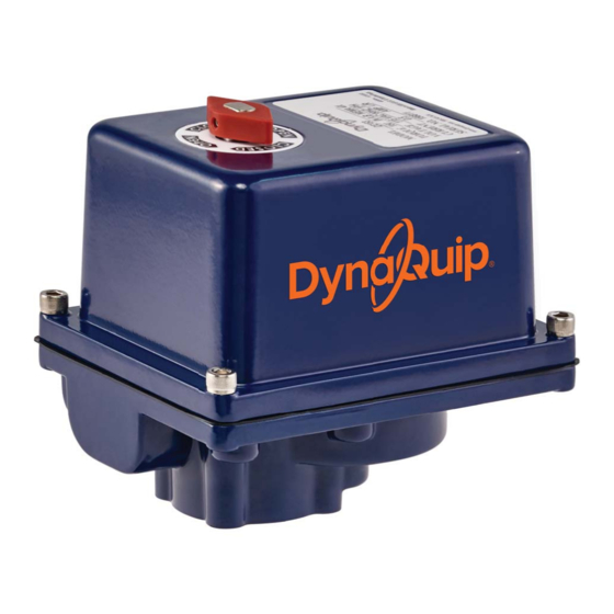
DynaQuip EVA Series Handbuch für Installation, Wartung und Betrieb - Seite 3
Blättern Sie online oder laden Sie pdf Handbuch für Installation, Wartung und Betrieb für Controller DynaQuip EVA Series herunter. DynaQuip EVA Series 12 Seiten.

SETTING OPEN POSITION 1B
If valve travels too far past open; Manually rotate shaft
CW past the open position. Follow instructions in 1A for
"Setting Open Position" .
SETTING CLOSE POSITION 2A
If valve did not close completely; Turn power off. Remove
cover. Loosen set screw in bottom cam and rotate
counterclockwise. Manually rotate shaft clockwise to
desired close position. Slowly rotate cam clockwise until
switch lever opens.
You should hear a light click. (To check using a multi-
meter: Set multi-meter to "Resistance" or "Continuity"
mode. Connect leads to terminals 3 & 5, rotate cam
clockwise until switch lever opens and continuity is
achieved.) Tighten set screw to set close position.
Wiring Diagrams
Electric Actuator Wiring Diagram
|
120 VAC/230 VAC
1 Phase
Field Wiring
SW1-Close
M
SW2-Open
SW2
SW1
1
2
3
4
5
6
+
AC Voltage
–
Power to Terminals:
•
1 and 2 to Open
•
1 and 3 to Close
•
Terminals 4 and 5 for field remote signals
•
SPDT switch is shown for illustration only
NOTE: Field wiring is shown for reference only: not supplied with the actuator.
|
50-60 Hz
T-Block "B"
(Optional)
N.C.
1
2
N.O.
3
COM
4
N.C.
5
N.O.
6
COM
SWT4
SWT3
SWT2
SWT1
SETTING CLOSE POSITION 2B
If valve closed too far; Manually rotate shaft
counterclockwise past close position. Follow instructions
in 2A for "Setting Close Position" .
Restore electric power to actuator and operate the
unit several times and recheck positions. If still out of
alignment, repeat setting cams for alignment.
Replace cover.
Maintenance
Under normal operation, electric actuators require
no formal maintenance program.
Regularly scheduled inspections should be performed to
check for:
•
Actuator-to-valve misalignment
•
Damaged housing or mounting hardware
•
Worn, loose or shifted parts due to shock,
vibration, etc.
Electric Actuator Wiring Diagram
|
12-24 VDC and 24 VAC
1 Phase
Field Wiring – Low Voltage
SW1-Close
M
SW2-Open
SW2
SW1
1
2
3
4
5
6
+
AC/DC Voltage
–
Power to Terminals:
•
1 and 2 to Open
•
1 and 3 to Close
•
Terminals 4 and 5 for field remote signals
•
+Power to 6 for heater operation
•
SPDT switch is shown for illustration only
T-Block "B"
(Optional)
1
N.C.
2
N.O.
3
COM
4
N.C.
5
N.O.
COM
6
SWT4
SWT3
SWT2
SWT1
3
