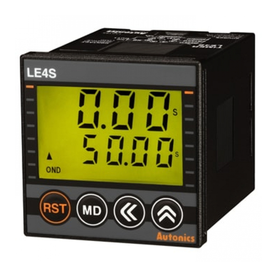
Autonics LE4SA Anleitung - Seite 10
Blättern Sie online oder laden Sie pdf Anleitung für Zeitschaltuhr Autonics LE4SA herunter. Autonics LE4SA 18 Seiten. Din w48xh48mm digital backlight lcd timer
Auch für Autonics LE4SA: Handbuch (17 seiten)

● Backlight ON/OFF setting
[Fig.6]
※ Factory default
● Key Lock setting
[Fig.7]
※ Factory default
Setting time change
Please set operation time according to following instruction as the setting is different depending on the output operation
mode.
● Output operation mode : OND, ONDⅠ, ONDⅡ, INT, INTⅠ, OFF D
(LE4SA does not have no ONDⅠ, INTⅠ, OFF D.)
[Fig.1]
1) Press
key in RUN mode, time set digits will flash.[Fig. 1]
2) Change setting time by using
-
key : Shift the setting digits.
-
key : Shift the flashing position value. As press
number will increase faster by press
3) When the setting is completed, it will be stored and return to RUN mode by pressing
1) In function setting mode, if it enter into Backlight ON/OFF setting mode, the characters will
be displayed as shown in the [Fig. 6].
2) Select Backlight ON or OFF using
3) Press
key to complete Backlight ON/OFF setting and move to the next mode.
4) If pressing
key for 3 sec. in any function setting mode, it will return to Run mode.
1) In function setting mode, if it enter into Key Lock setting mode, the characters will be
displayed as shown in the [Fig. 7].
2) Select
,
,
lOFF
LOc1
LOc2
key
key
Blank
Turns off
the Lock mode.
cannot be used.
3) Press
key to complete key lock setting and move to the next mode.
4) If pressing
key for 3 sec. in any function setting mode, it will return to Run mode.
※ Factory default for LE4S is
※ Key Lock function
Display
Function
Turns off the key Lock mode.
lOFF
key cannot be used.
LOc1
,
LOc2
,
LOc3
[Fig.2]
or
key.[Fig. 2,3,4]
key once, it will increase by 1digit,
key for over 2sec.
LCD Timer(Touch Type)
,
key.
key
key
or
using
,
key.
LOc3
key
key
key
key
key
,
key
cannot be used.
and Factory default for LE4SA is
lOFF
key cannot be used.
,
key cannot be used.
[Fig.3]
[Fig.4]
key
key
,
,
key
cannot be used.
.
LOc1
[Fig.5]
key.[Fig. 5]
(A)
Photo
electric
sensor
(B)
Fiber
optic
sensor
(C)
Door/Area
sensor
(D)
Proximity
sensor
(E)
Pressure
sensor
(F)
Rotary
encoder
(G)
Connector/
Socket
(H)
Temp.
controller
(I)
SSR/
Power
controller
(J)
Counter
(K)
Timer
(L)
Panel
meter
(M)
Tacho/
Speed/ Pulse
meter
(N)
Display
unit
(O)
Sensor
controller
(P)
Switching
mode power
supply
(Q)
Stepper
motor&
Driver&Controller
(R)
Graphic/
Logic
panel
(S)
Field
network
device
(T)
Software
(U)
Other
K-29
