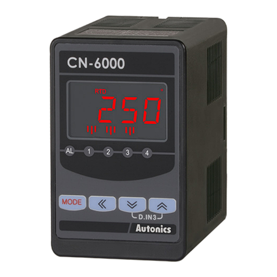
Autonics CN-610 Series Produkthandbuch - Seite 5
Blättern Sie online oder laden Sie pdf Produkthandbuch für Medienkonverter Autonics CN-610 Series herunter. Autonics CN-610 Series 6 Seiten. Isolated converters

Input Type and Using Range
■ Universal input
Input type
Cu50 Ω
Cu100 Ω
RTD
JPt100 Ω
DPt50 Ω
DPt100 Ω
K (CA)
J (IC)
E (CR)
T (CC)
B (PR)
Thermocouple
R (PR)
S (PR)
N (NN)
C (W5)
L (IC)
U (CC)
Platinel II
0.00 - 20.00 mA
4.00 - 20.00 mA
-50.0 - 50.0 mVDCᜡ
Analog
-199.9 - 200.0 mVDCᜡ
-1.000 - 1.000 VDCᜡ
-1.00 - 10.00 VDCᜡ
■ Pulse input
• Non-contact: 0 to 50 kHz / contact: 0 to 45 kHz
Displays 0 for below 0.1 Hz
• Input Low Level: 0 - 1 VDCᜡ / Input High Level: 5 - 24 VDCᜡ
• Duty ratio: 30 to 70 %
• Since the response speed is slower in the low-speed pulse, 0 Hz is displayed if no pulse is
input for more than 2 sec to prevent the slow response speed at 0 Hz.
Input type
Measuring cycle Display Using range
0 to 9.999 Hz
≤ 10 sec
0 to 99.99 Hz
≤ 10 sec
Pulse
0 to 999.9 Hz
≤ 10 sec
0 to 9.999 kHz ≤ 1 sec
0 to 50.00 kHz ≤ 0.1 sec
Reset
01. Press the [MODE] + [◀] keys in run mode, parameter INIT is displayed.
02. Displays the setting value as NO by pressing the [MODE] key.
03. Change the setting value as YES by pressing the [▲] or [▼] keys.
04. Press the [MODE] key to reset all parameter values as default and to return
to run mode.
• Reset is possible when the lock parameter of the program mode is set to OFF.
Error
Display
Description
Flashes when measurement input is lower
than the using range
LLLL
Flashes when measurement input is higher
than the using range
HHHH
Flashes when the temperature sensor is
01) 02)
disconnected
BURN
Flashes when setting value error
ERR
Flashes when the parameter setting of the
input type and the selection switch setting
01)
ERR2
do not match.
01) Applicable to universal input model only.
02) Transmission output and alarm output according to P1-36 sensor disconnection alarm output parameter
setting.
Sensor disconnection
Transmission output
alarm output
(DC 4 - 20 mA)
ON
20 mA
OFF
4 mA
Display Using range ( ℃)
Using range (℉)
Cu50 -199.9 to 200.0
-199.9 to 392.0
Cu10 -199.9 to 200.0
-199.9 to 392.0
JPt1 -199.9 to 600.0
-328 to 1112
DPt5 -199.9 to 600.0
-328 to 1112
DPt1 -199.9 to 850.0
-328 to 1530
TcK1 -200 to 1350
-328 to 2462
TcK2 -199.9 to 999.9
-328 to 1832
TC-J -199.9 to 800.0
-328 to 1472
TC-E -199.9 to 800.0
-328 to 1472
TC-T -199.9 to 400.0
-199.9 to 752.0
TC- B 400 to 1800
752 to 3272
TC-R 0 to 1750
32 to 3182
TC-S 0 to 1750
32 to 3182
TC-N -200 to 1300
-328 to 2372
TC-C 0 to 2300
32 to 4172
TC-L -199.9 to 900.0
-328 to 1652
TC-U -199.9 to 400.0
-199.9 to 752.0
TC-P 0 to 1390
32 to 2534
aMA1
aMA2
-1999 to 9999
• The using range varies depending on the
aMV1
decimal point position.
aMV2
A-V1
A-V2
10H
-1999 to 9999
100H
• The using range varies depending on the
1KH
decimal point position.
10KH
50KH
Troubleshooting
Error display is released
automatically when it is in the
measured and using range.
Check the input sensor status.
Resetting after checking the
setting conditions.
Check the input type.
Alarm output
High-limit alarm Low-limit alarm
ON
OFF
OFF
ON
Alarm Output
The alarm output is set by combining the alarm operations and alarm
88* 8
options.
Each alarm output operates independently, and the alarm is
Alarm
Alarm
automatically canceled when the current temperature exceeds the
operation
option
alarm operating range.
■ Operation
Name
SV
Alarm operation
No alarm
AT0
-
output
High-limit
AT1
alarm
High-limit input value: 800 ℃
ON
H
Low-limit
AT2
200 ℃: Low-limit input value
alarm
PV
Sensor break
SBA -
alarm
■ Option
Name
SV
Description
Standard
If it is an alarm condition, alarm output is ON. Unless an alarm
A
alarm
condition, alarm output is OFF.
If it is an alarm condition, alarm output is ON. Before clearing the
Alarm latch
B
alarm, an ON condition is latched. (holding the alarm output)
First alarm condition is ignored. From the second alarm
Standby
condition, standard alarm operates.
C
sequence
• When power is ON and it is an alarm condition, it is ignored. From
the second alarm condition, standard alarm operates.
If it is an alarm condition, it operates both alarm latch and
Alarm latch
standby sequence.
and standby
D
• When power is ON and it is an alarm condition, it is ignored.
sequence
From the second alarm condition, alarm latch operates.
■ Alarm output hysteresis
The set hysteresis is applied to AL1 to AL4 and it is as below.
• E.g.: high-limit input value: 800 ℃, low-limit input value: 200 ℃, hysteresis: 4
800 ℃
796 ℃
Alarm
ON
OFF
output
Hold
Holds current display value and control output when external input signal is applied.
Input:
Display:
■ When not using hold function
Input/
Display
Detection area
Time
Output
ON
OFF
Time
■ When using hold function
Input
Display
Detection area
Output
ON
OFF
Hold input
• H: alarm output hysteresis
Alarm output ON
-
OFF
H
ON
PV ≥ High-limit input value
PV
OFF
PV ≤ Low-limit input value
When sensor disconnection
is detected
204 ℃
4
200 ℃
Alarm
ON
output OFF
Detection area
Output
ON
OFF
Detection area
Time
Output
ON
OFF
Time
Hold input
4
Input/
Display
Time
Time
Display
Input
입력
Time
Time
