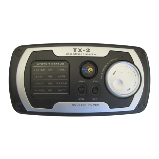
High Tech Pet Bluefang TX-2 Installations-, Betriebs- und Schulungshandbuch - Seite 6
Blättern Sie online oder laden Sie pdf Installations-, Betriebs- und Schulungshandbuch für Haustierpflegeprodukt High Tech Pet Bluefang TX-2 herunter. High Tech Pet Bluefang TX-2 9 Seiten. Electronic fence

Set Up the Base Station Transmitter
Assemble the Required Tools
Here is the list of tools you will need.
1. Straight edge spade or power edger
2. Wire cutter/stripper
3. Power drill with 1/8" drill bit
4. Phillips screwdriver or Phillips driver bit for your drill
The TX-2 casing is assembled in two parts, the mounting base and the
electronics console. In the package, they are assembled together. You must first
separate the mounting base from the console. This is easily done by simply
pulling them apart. Hold the mounting base in one hand and the console in the
other and firmly pull apart. The snap closures will separate. Using the four
mounting screws provided, mount the Mounting Base in its desired location. If
you have purchased the optional back-up battery, install it in the back of the
electronics console by plugging in the connector and snapping the battery into
place. If you did not purchase the back-up battery it is easy to install it at a later
date should you choose to do so.
Mounting:
Indoor mounting of the TX-2 Base Station Transmitter is preferred.
However, if your layout prohibits indoor mounting, it is acceptable to
mount the TX-2 outdoors. Although the casing is water-sealed, you
should still choose a location that is not directly exposed to rain, wind
and other adverse weather.
AC Adapter: Plug the 16 VDC adapter into a standard 115 Volt outlet and
connect the DC plug into the receptacle on the lower right of the Base Station
Transmitter.
Test The Receiver Collar Radio Function
You should test the receiver by installing a 24 inch long test loop of wire
across the quick connect cable terminals. Set the Power Boost switch
to normal (NOR) and switch on the Base Station Transmitter. Bring the
receiver close to your test loop. A beeping sound emitted by the receiver
collar indicates the system is working properly. Note that with such a short
loop the range will only be a few inches.
Prepare Twisted Wire Lengths First
Prepare the twisted lengths of wire. From your system layout sketch,
determine the length required for each twisted pair. Cut two equal lengths
of wire for each required twisted pair. With the pair of wires side by side,
put one end of each wire in a power drill and spin the wires until there is
approximately one twist per inch of wire. Do not over-twist because this
could damage the wire. Repeat for each required pair.
Layout the Boundary Wire Above Ground
Before burying your boundary wire, we recommend that you run the
complete loop of wire, make all connections and use the receiver collar to
fully test the system with the wire above ground. Referring to the sketch you
made of your system layout, run and connect the wire loop above ground,
connect it to the Transmitter Base Station.
Installation Tip: Leave a little (about 15 inches) slack in the wire
periodically along the perimeter and at the corners of the layout so you
have a little extra wire when needed to repair a break in the loop. Wind
the 15 inch slack into a 5 inch diameter coil and bury it with the wire.
Choose locations for the slack that are easily identified by a terrain
feature and make a map of them.
10
11
