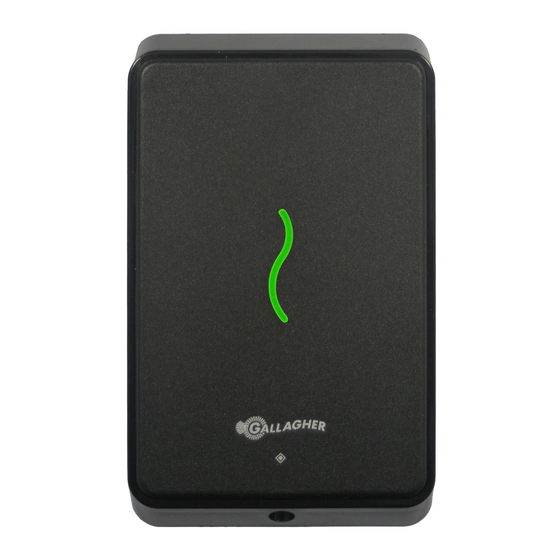
Gallagher C300411 Hinweis zur Installation - Seite 5
Blättern Sie online oder laden Sie pdf Hinweis zur Installation für Kartenleser Gallagher C300411 herunter. Gallagher C300411 13 Seiten.

2
Before you begin
2.1
Shipment contents
Check the shipment contains the following items:
•
1 x Gallagher T11 Reader facia assembly
•
1 x Gallagher T11 Reader bezel
•
1 x M3 Torx Post Security screw
•
2 x 6-32 UNC Phillips drive fixing screws
•
4 x 25 mm No.6 self tapping, pan head, Phillips drive fixing screws
•
4 x 40 mm No.6 self tapping, pan head, Phillips drive fixing screws
2.2 Power supply
The Gallagher T11 Reader is designed to operate over a supply voltage range of 9 - 16 Vdc
measured at the reader terminals. The operating current draw is dependant on the supply
voltage at the reader. For the Mifare reader, at 13.6 Vdc the current draw is 84 mA (idle). During
card read, beeper and LED activity, the current will momentarily reach 113 mA (maximum). For
the Multi Tech reader, at 13.6 Vdc the current draw is 100 mA (idle) and will momentarily reach
124 mA (maximum). The power source should be linear or a good quality switched-mode power
supply. The performance of the reader may be affected by a low quality, noisy power supply.
2.3 Cabling
The Gallagher T11 Reader requires a minimum cable size of 4 core 24 AWG (0.2 mm
security cable. This cable allows the transmission of data (2 wires) and power (2 wires). When
using a single cable to carry both power supply and data, both the power supply voltage drop
and data requirements must be considered. Although the reader is specified to operate at 9
Vdc, for good engineering design it is recommended that the voltage at the reader should be
approximately 12 Vdc.
HBUS cabling topology
The HBUS communications protocol is based on the RS485 standard and allows the reader to
communicate over a distance of up to 500 m (1640 ft).
The cabling between HBUS devices should be done in a "daisy chain" topology, (i.e. A "T" or
"Star" topology should not be used between devices). Should "Star" or "Home-Run" wiring be
required, the HBUS 4H/8H Modules and the HBUS Door Module allow multiple HBUS devices to
be individually wired to the one physical location.
The end devices on the HBUS cable should be terminated using 120 ohms resistance. To
terminate the Gallagher Controller 6000, connect the supplied on-board termination jumpers
to the Controller. To terminate a reader, connect the orange (termination) wire to the green
(HBUS A) wire. Termination is already included at the HBUS Module, (i.e. each HBUS port is
permanently terminated at the module).
3E4289 Gallagher T11 Reader | Edition 1 | August 2016
Copyright © Gallagher Group Limited
) stranded
2
Page 5
