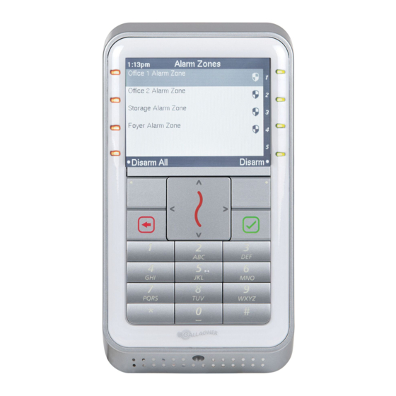
Gallagher T20 Hinweis zur Installation - Seite 2
Blättern Sie online oder laden Sie pdf Hinweis zur Installation für Kartenleser Gallagher T20 herunter. Gallagher T20 14 Seiten.

Gallagher T20 Reader
IMPORTANT: Gallagher T20 Multi Tech readers only:
Using dual technology 125/Mifare cards with Gallagher T20 Multi Tech readers
may cause both card technologies to be read, resulting in double card badges
and unusual reader feedback. Gallagher strongly recommends against using dual
technology 125/Mifare cards with Gallagher Multi Tech readers for sites running
pre-Command Centre v7.00 software. From Command Centre v7.00, a site may
specify which technology a Multi Tech reader should read off a dual technology
card.
Before you begin
Shipment Contents
Check the shipment contains the following items:
•
1 x Gallagher T20 Reader facia assembly
•
1 x Gallagher T20 Reader base
•
2 x 6-32 UNC Phillips drive fixing screws
•
2 x M3.5 Phillips drive fixing screws
•
5 x 25 mm No.6 self tapping, pan head, Phillips drive fixing screws
•
5 x 40 mm No.6 self tapping, pan head, Phillips drive fixing screws
•
1 x M3 Torx Post (T10) Security screw
Power Supply
The Gallagher T20 Reader is designed to operate over a supply voltage range
of 9 - 16 Vdc measured at the reader terminals. The operating current draw is
dependent on the supply voltage at the reader. For the Mifare reader, at 12 Vdc
the current draw is 90 mA (standby). During card read, beeper and LED activity, the
current will momentarily reach 125 mA (peak). For the Multi Tech reader, at 12 Vdc
the current draw is 90 mA (standby) and will momentarily reach 140 mA (peak).
The power source should be linear or a good quality switched-mode power supply.
The performance of the reader may be affected by a low quality, noisy power supply.
Cabling
The Gallagher T20 Reader requires a minimum cable size of 4 core
24 AWG (0.2 mm
data (2 wires) and power (2 wires). When using a single cable to carry both power
supply and data, both the power supply voltage drop and data requirements must
be considered. Although the reader is specified to operate at 9 Vdc, for good
engineering design it is recommended that the voltage at the reader should be
approximately 12 Vdc.
Examples of approved cables for connecting a single Gallagher T20 Reader to a
Controller and power supply, showing maximum cable lengths for each type of cable
and the associated circuits are:
Page 2
) stranded security cable. This cable allows the transmission of
2
Installation Note
Document Code: 3E3140
Edition 3, April 2013
