Maico 0084.0362 Installations- und Betriebsanleitung - Seite 11
Blättern Sie online oder laden Sie pdf Installations- und Betriebsanleitung für Fan Maico 0084.0362 herunter. Maico 0084.0362 16 Seiten. Er ec covers for er ec flush-/surface-mounted exhaust air systems (according din 18017-3)
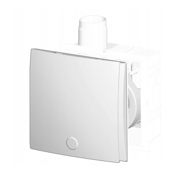
9.3 Removing fan insert
1,
Cover – upper
7
part
16 Central screw
1. Before removing the fan insert, switch off all
supply circuits (switch off mains fuse), secure
against being accidentally switched back on
and position a visible warning sign.
2. Remove the cover. To do so, swivel the upper
part of the cover upwards, remove air filter,
unscrew the central screw and carefully re-
move the entire upper part.
3. Press the 3 locking hooks of the stud together
and evenly pull the fan insert out of the hous-
ing in parallel.
The degree of protection, according to the
rating plate, is only ensured if properly in-
stalled (fan insert correctly engaged).
10 Installing the cover ER-A, ER-
AK, ER-AH, ER-AB
It is possible to rotate the cover by ± 5° to
compensate for housings which have been fit-
ted at an angle.
1. ER-AK, ER-AH, ER-AB: Pull off the sealing
plugs from the motor board interface (Fan in-
sert [} 10]).
2. Plug cover's flat cable with plug into interface
connector. Ensure correct connection.
10 Installing the cover ER-A, ER-AK, ER-AH, ER-AB
2,
Cover – lower
4,
part
5,
8
17 Air filter
3. ER-A, ER-AK, ER-AH, ER-AB: Screw cover
to the fan insert with the central screw. If in-
stalling on a wall, ensure that the Maico name
is on the bottom right.
4. Insert air filter and fold down the upper part of
the cover (upper part must audibly engage).
5. Run function test: Test all unit functions (over-
run time, interval, humidity control etc.).
For ER-A, no setting functions. For ER-AK,
ER-AH, ER-AB, the operating parameters
can be changed.
11 Operating the unit
ER EC fans run at 30 m³/h in base load opera-
tion (factory setting).
A light switch or separate switch can be used to
switch to full-load operation with 60 m³/h.
The unit control is located in the cover: ER-AK,
ER-AH and ER-AB have automatic functions with
unit parameters that can be set: Covers: Functions
[} 8].
• ER-A: Standard model
• ER-AK: Comfort model
• ER-AH: Model with humidity control, barrier-free
• ER-AB: Model with motion sensor, barrier-free
For full load operation, a start delay of 60
seconds and an overrun time of 15 minutes are
specified at the factory.
Ensure sufficient supply air during opera-
tion.
The factory settings correspond to
DIN 18017-3. If the set parameters are
changed when operating with cover ER-AK,
ER-AH or ER-AB, function in accordance with
DIN 18017-3 is not always ensured. The
planer/installer is responsible for operation in
accordance with standards.
In the event of overload (blocking), the fan
switches off automatically.
11