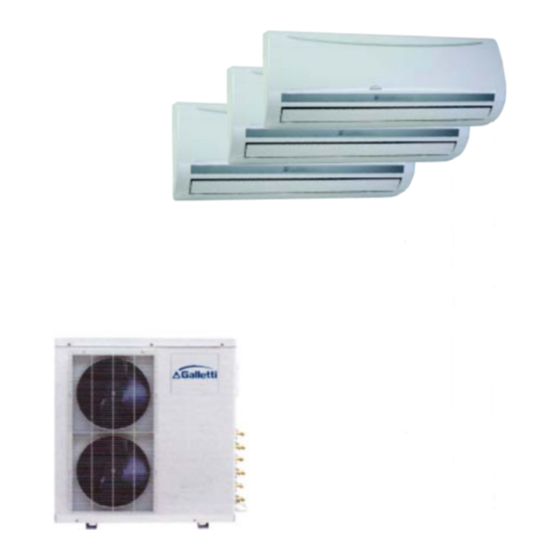
Galletti MS 999 H Handbuch für Installation und Wartung - Seite 5
Blättern Sie online oder laden Sie pdf Handbuch für Installation und Wartung für Zubehör für Klimageräte Galletti MS 999 H herunter. Galletti MS 999 H 16 Seiten. Multisplit with high wall indoor units
Auch für Galletti MS 999 H: Benutzerhandbuch (16 seiten)

MS
MS
MS
MS
MS
Tassello ad espansione
Vite di fissaggio A ST3.9x25-C-H
Mounting screw A ST3.9x25-C-H
Unità
unit
Comando a distanza
Remote controller
Tassello ad espansione
Vite di fissaggio A ST3.9x25-C-H
Clip anchor
Mounting screw A ST3.9x25-C-H
Unità
unit
Comando a distanza
Remote controller
Tassello ad
Vite di fissaggio A
espansione
ST3.9x25-C-H
Clip anchor
Mounting screw A
4,3cm
ST3.9x25-C-H
Unità
unit
Vite di fissaggio B 2.9x10-C-H
Mounting screw B 2.9x10-C-H
Comando a distanza
Remote controller
È severamente vietata la riproduzione anche parziale di questo manuale / All copying, even partial, of this manual is strictly forbidden
Clip anchor
4,3cm
Piastra di fissaggio
Installation plate
Vite di fissaggio B 2.9x10-C-H
Mounting screw B 2.9x10-C-H
Supporto per comando
a distanza
Remote controller
holder
4,3cm
Piastra di fissaggio
Installation plate
Vite di fissaggio B 2.9x10-C-H
Mounting screw B 2.9x10-C-H
Supporto per comando
a distanza
Remote controller
holder
Piastra di fissaggio
Installation plate
Supporto per comando
a distanza
Remote controller holder
UNITA INTERNA
INDOOR UNIT
Praticare il foro per
il tubo in modo da
consentire una
leggere pendenza.
Cut the pipe hole
sloped slightly.
I tubi possono essere collegati posteriormente, a destra o a sinistra o in basso.
Piping can be connected from the rear, left right or bottom.
Destra
Right
Posteriore in
Posteriore a
basso
sinistra
Bottom rear
Rear left
Collegare il tubo ausiliario delle tre unità interne alle valvole di arresto come
identificato con i rispettivi numeri di accoppiamento A1, A2 e B posti sull'unità
esterna. Terminato il collegamento, le unità interne debbono essere
contrassegnate rispettivamente con i numeri A1, A2 e B.
Connect the auxiliary pipe of the three indoor units to the stop valves as
identified with their respective matched numbers A1, A2, and B on the
outdoor unit. After finishing connection, the indoor units must be marked
relative number A1, A2 and B.
UNITA ESTERNA
OUTDOOR UNIT
Collegare il cavo (lunghezza
circa 300 mm)
Loop the connective
cable(about 300 mm long).
Vite di fissaggio C 3.9x10-C-H
Mounting screw C 3.9x10-C-H
Vaschetta raccogli condensa
Water tray
5
Montaggio delle
How to mount the
tubazioni destre e
left and rear-left
sinistre
piping
Il collegamento della
Piping can easily be
tubazione può essere
made by lifting the
effettuato facilmente
indoor unit with a
sollevando
l'unità
cushioning material
interna con materiale
at
the
elastico posto tra l'unità
controller holder side
stessa e la parete, in
between the indoor
corrispondenza del lato
unit and the wall.
del
supporto
del
comando a distanza.
Il tubo flessibile di
Do not allow the
scarico
non
deve
drain hose to get
allentarsi.
slack.
Fare attenzione che il
Make sure to run
tubo di scarico abbia
the
drain
un'inclinazione verso il
sloped downward
basso.
Sinistra
Left
NOTA
NOTE
SY66000058 - 02
remote
hose
