Galls ST160 SIREN Installations- und Betriebsanleitung - Seite 5
Blättern Sie online oder laden Sie pdf Installations- und Betriebsanleitung für Verstärken Galls ST160 SIREN herunter. Galls ST160 SIREN 7 Seiten. Siren amplifier
Auch für Galls ST160 SIREN: Installations- und Betriebsanleitung (12 seiten)
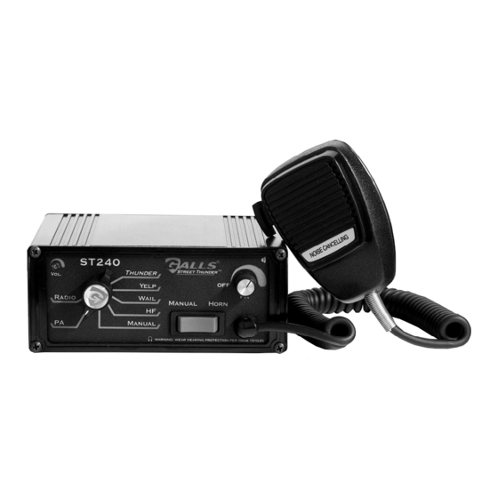
VOLUME CONTROLS
The radio repeat volume (Radio) control is recessed in
the upper left hand corner of the front face. This
should be set when the vehicle is parked. First set the
volume level of the vehicle's two-way radio to its
normal operating volume. Adjust the siren's rotary
selector switch into the RADIO position. Insert a
small, flat blade screwdriver into the RADIO volume
adjustment port. Turn clockwise direction to increase
the sound level.
The PA volume (PA Vol.) control is provided for public
address volume. It is located in the upper right hand corner
of the front face. This should be set when the vehicle is
parked. Set the PA volume to the maximum level with no
feedback (squeal).
MICROPHONE
The attached noise-canceling microphone is used for public address operation and
overrides any siren tone when its push-to-talk (button on the side) is pressed.
AUXILIARY INPUT
During installation an auxiliary input may be connected to the vehicle horn ring or
other switching device. It provides the same operation as pressing the Horn button
or optionally (via internal jumpers) the Manual rocker switch.
PARK KILL (CUTOUT)
During installation, the Park Kill input may be connected to a door switch. It will
automatically turn off any siren tone when the door is opened. The siren tone will
continue to be cut off even when the door is closed. Changing any switch or input
will restore normal function.
-9-
MOUNTING
SAFETY PRECAUTIONS
For the safety of the installer, vehicle operator, passengers and the community
please observe the following safety precautions. Failure to follow all safety
precautions and instructions may result in property damage, injury or death.
!!! WARNING !!!
DO NOT mount in air bag deployment area.
Devices should be mounted only in locations listed in SAE standard J1849.
Controls should be placed within convenient reach of the driver.
Assure clearances before drilling in vehicle.
To prevent internal damage, the mounting bolts must not enter case more
than 1/4".
Sound levels produced by attached speakers can cause permanent hearing loss.
Never operate this unit without adequate hearing protection for you and others
in the area. (OSHA 1910.95)
The ST160 siren may be mounted above the dash, below the dash, on a tunnel, or in
a rack with the mounting u-bracket provided. Choose a mounting location
convenient to the operator and away from any air bag deployment areas. Inspect
behind mounting area for clearance. Assure adequate ventilation to prevent
overheating. Consider wire routing and access to connections, as well as
microphone bracket placement. Install mounting bracket to vehicle using 1/4"
hardware (not supplied). Drill two 1/8" size holes, and install microphone clip
using the two screws provided with the clip.
ELECTRICAL CONNECTIONS
Electrical connections to the unit are made using a removable connector located on
the back. If the unit needs service the connector can be easily removed without
unwiring the connector.
The power supply of the unit must be capable of delivering peak currents up to 50
amps for adequate short circuit protection and reliable operation. The preferred
source is directly at the vehicle battery. The unit is internally fused. A wiring
diagram on the next page shows detail of how to wire the siren to the vehicle.
-4-