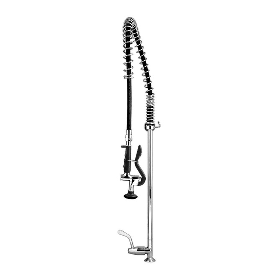
Galvin Engineering Ezy-Wash TF81HJP Produkt-Installations-Manualline - Seite 3
Blättern Sie online oder laden Sie pdf Produkt-Installations-Manualline für Sanitärprodukt Galvin Engineering Ezy-Wash TF81HJP herunter. Galvin Engineering Ezy-Wash TF81HJP 5 Seiten. Pre-rinse tapware

Version 1, 3 August 2017, Page 3 of 5
INSTALLATION
INSTALLATION COMPLIANCE: Galvin Specialised products must be installed in accordance with these
installation instructions and in accordance with AS/NZS 3500, the PCA and your local regulatory requirements.
Water and/or electrical supply conditions must also comply to the applicable national and/or state standards.
Failing to comply with these provisions shall void the product warranty and may affect the performance of the
product.
1. Measure and cut support rod
Measure the distance between the wall mounting
surface and the centre line of the drilled hole in
the bench/trough (dimension "A").
Take dimensions "A" and subtract 16mm. This is
the required length of the support rod (Required
support rod length = A-16mm).
Cut the support rod accordingly; ensure the
threaded end is NOT cut off.
Note: Distance "A" must be no less than 70mm.
The support rod length can be 70mm min. to 285mm
max. (If it is more than 285mm, an extension support
rod must be purchased)
3. Fit support rod
If pot filler kit (TF81HJP) has been purchased, it
must be attached to the pre-rinse unit prior to
fitting the support rod to the riser. Refer to the
installation instruction supplied with the pot
filler.
Screw support rod into the riser hook and
ensure it is not fully tightened.
Version 2, 3 August 2017, Page 3 of 5
2. Fit wall bracket
Secure the wall bracket to the wall.
Supplied fasteners may not be suitable for
the mounting surface. If this is the case,
suitable fasteners will need to be sourced.
Note: The wall bracket must be mounted with three
screws for stability and strength. This is critical
and failure to do this may void the warranty.
4. Fit upper riser to lower riser
Remove protective cap from upper riser
spindle.
Fit the upper riser to the lower riser, ensure
the sealing o-rings are inside the spindle.
Tighten with new supplied grub screw.
It is critical that the grub screw point
locates accurately into hole recess of
mating part. Failure to do so may result in
damage and/or failure of the unit.
