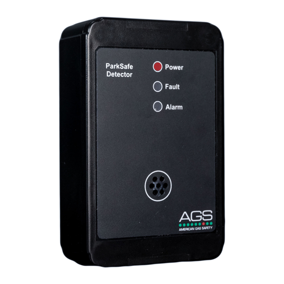
AGS Parksafe Control Panel Handbuch für Installation, Betrieb und Wartung - Seite 5
Blättern Sie online oder laden Sie pdf Handbuch für Installation, Betrieb und Wartung für Controller AGS Parksafe Control Panel herunter. AGS Parksafe Control Panel 20 Seiten. Ventilation control panel
Auch für AGS Parksafe Control Panel: Handbuch für Installation und Betrieb (16 seiten), Handbuch für Installation und Betrieb (16 seiten), Installation, Betrieb und Wartung (16 seiten)

Installation, Operation & Maintenance
ParkSafe Detector Placement Plan
The relative density of carbon monoxide compared to air of carbon monoxide is 0.957 (AIR =1). The carbon
monoxide will disperse evenly in the air. The carbon monoxide monitors must be located as specified by your
region's building code. If not specified contact your local AGS representative. Detection of nitrogen dioxide is
done where a significant quantity of diesel engines is typically located such as train stations, bus and truck
maintenance garages, rapid transit authorities, car dealerships, ambulance bays, loading docks and diesel-
powered vehicle parking structures. ParkSafe detectors should be mounted where a potential hazard of gas is
most likely to be present. The following points should be noted when locating gas sensors. When locating
detectors consider
The possible damage caused by natural events e.g., Rain or flooding.
•
Ease of access to the gas detector for functional testing and servicing.
•
How gas may behave due to natural or forced air currents.
•
The quantity of sensors is determined by the following rules of thumb:
The radius of coverage is 50 feet (15.2 metres) per detector or 7,580
1.
square feet (704.2 square metres).
Use open interior support columns as much as possible to maximize the radius of coverage.
2.
Each level of the parking structure must be totally covered without overlapping the coverage of the sensors.
3.
Mounting & Cabling
Where cable glands/conduits are used for wire entry, use no bigger than 20mm (3/4") separated by at least 20mm (1/2")! Any parts
that form part of the connections/installation must have a minimum fire-retardant rating of UL 94 V-1!
Restrain the hazardous live wiring from accidental loosening to prevent wires from moving after installation and touching parts of
opposite polarity or at low voltages!
Designed for surface mounting, it must be installed by a licensed, insured contractor!
Carefully remove the front cover from the unit by unscrewing the four M6 hex bolts located at each corner.
To do this – use the socket wrench provided.
Ensure the wall surface is solid and flat to prevent base distortion and mark the four 6mm (0.236") screw holes
located on the back of the enclosure to the wall.
Use a suitable screw/bolt (M4x30min) and appropriate expanding plug to fix the back of the enclosure to the
wall surface. Drill out as necessary ensuring all swarf is removed from the box and holes have smooth edges.
After executing the mounting and the electrical connections – replace the front cover and insert the security
caps over the four M6 hex bolts.
Rev: 20
ParkSafe Controller
5
