Dynojet Power Comander III Einbauanleitung - Seite 3
Blättern Sie online oder laden Sie pdf Einbauanleitung für Zubehör für Motorräder Dynojet Power Comander III herunter. Dynojet Power Comander III 4 Seiten. 2004-2007 kawasaki
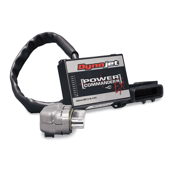
wires from
PCIII USB EX
throttle body
PCIII USB EX connectors
wire tap connector attaches
to the yellow wire with the
white stripe
i215-411EX
stock connectors
wire from PCIII USB EX
harness
Closer view of the PCIII USB EX harness.
7
Attach the female PCIII USB EX connector with
the orange/white wire to the front injector as
shown in Figure E.
8
Attach the male PCIII USB EX connector with
the orange wire to the stock injector connector
as shown in Figure E.
9
Attach the female PCIII USB EX connector with
the yellow/white wire to the rear injector as
shown in Figure E.
10 Attach the male PCIII USB EX connector with
the yellow wire to the stock injector connector
as shown in Figure E.
11 Locate the wires coming from the throttle
position sensor as shown in Figure F.
12 Attach the supplied wire tap to the yellow wire
with the white stripe as shown in Figure F.
Firm pressure is required to close the
connector.
13 Attach the grey wire with the spade terminal
from the PCIII USB EX to the wire tap as shown
in Figure F. It is recommended to seal this
connector with dielectric grease.
2004-2007 Kawasaki Mean Streak - PCIII USB EX - 3