AGS Parksafe Control Panel Handbuch für Installation und Betrieb - Seite 6
Blättern Sie online oder laden Sie pdf Handbuch für Installation und Betrieb für Bedienfeld AGS Parksafe Control Panel herunter. AGS Parksafe Control Panel 16 Seiten. Ventilation control panel
Auch für AGS Parksafe Control Panel: Handbuch für Installation und Betrieb (16 seiten), Installation, Betrieb und Wartung (16 seiten), Handbuch für Installation, Betrieb und Wartung (20 seiten)

Installation & Operation Manual
Parksafe Detector Identification
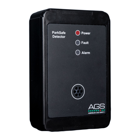
When wiring multiple detectors to the Parksafe panel it is important to identify each detector
and in which monitoring zone the detector is located for the Park Safe system to receive and
display data. Detector ID switches are fitted to detector circuit boards.
For more information refer to your Parksafe detector manual.
Detector Chain Termination Resistor Switch
Signal communication issues may occur where the bus length is too long or
high baud rates are used. In this instance – terminating at each end of the
chain may help the quality of the data signal. To do this - turn on the
[CHAIN TERMINATION RESISTOR] switch.
For more information refer to your Parksafe detector manual.
Settings Switch
On the front display circuit board you'll find a SETTINGS
switch – when switched to ON, the screen will display
the settings menu – you can now configure your
Parksafe system.
When changes have been made – turn the SETTINGS
switch off and the system will automatically restart.
Settings Menu
The Parksafe panel has a touch screen which allows the engineer/ user to configure the system.
Adjust the screen brightness.
(Press or slide the cursor up and down)
AGS Parksafe - IOM Iss: DRAFT 3 06-20
Change/select option.
(Press the blue option box or press and hold)
Parksafe Control Panel
6
