Main Access 200400T Montageanleitung - Seite 2
Blättern Sie online oder laden Sie pdf Montageanleitung für Leitern Main Access 200400T herunter. Main Access 200400T 2 Seiten. Easy entry step

Model #200400T
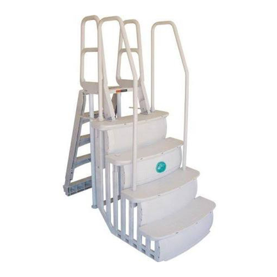
Easy Entry Step Components
Qty
A1) Upper Step Tread
1
A2) Lower Step Tread
1
B1) Upper Left Side Riser
1
B2) Lower Left Side Riser
1
C1) Upper Right Side Riser
1
C2) Lower Right Side Riser
1
D) Ballast Tray
1
E1) Upper Handrails
2
E2) Lower Handrails
2
F) Top Step Support Brace
1
G) Mid Riser Brace
1
H) Deck Connectors
2
I) Riser Cross Braces
2
J) Handrail Connectors
2
K) Step Tread Connector
1
L) Handrail Socket Caps
3
Hardware Kit (not shown)
Qty
M) Ballast Sand Bags
3
N) #8 x 1" SS Screws
18
O) #14 x 1-1/4" SS Screws
8
P) #10 x 3/4" SS Screws
9
S T E P B Y S T E P A S S E M B LY I N S T R U C T I O N S
Fig. 1
Fig. 2
A2
A1
EASY ENTRY STEP ASSEMBLY INSTRUCTIONS
E1
J
H
E2
C1
F
G
D
I
A1
B1
K
A2
B2
L
(Caps)
Step 1 Step Tread Assembly
Position the Step Tread Connector (K) and the
Upper Step Tread (A1) as shown. Be sure to
position the Step Tread Connector with the
tapered side towards the top of the step as
shown. Align all connectors and snap in place
(see Fig. 1). Be sure all connectors are firmly
secure. Repeat this process with the Lower
Step Tread (A2).
As indicated in Fig. 2, use nine (9) #10 x 3/4"
SS screws to secure the Upper and Lower Step
Treads to the Step Tread Connector. DO NOT
OVERTIGHTEN!
A second person will be of assistance in holding the side risers in place as it is being secured to the step treads.
A2
B2
C2
G
C2
Step 2 Right Riser Assembly
Position the Step Tread Assembly on its side as shown. Align the "mushroom
head" snaps with holes on the Lower Right Side Riser (C2). Once all snaps
and alignment holes are in position, firmly hold down the riser and strike
with a rubber mallet to secure the "mushroom heads" to the riser. Repeat
this process with the Upper Right Side Riser (C1).
Step 3 Left Riser Assembly
Position the Step Tread Assembly on its side as shown. Align the "mushroom
head" snaps with holes on the Lower Left Side Riser (B2). Once all snaps
and alignment holes are in position, firmly hold down the riser and strike
with a rubber mallet to secure the "mushroom heads" to the riser. Repeat
this process with the Upper Left Side Riser (B1).
F
Step 4 Step Braces / Ballast Tray
Locate the Top Step Support Brace (F). Position the brace with the open
side facing toward the front of the step. Be sure to position the brace so
the notch on each end will align and be flush with the top side of each
riser. Locate the Mid-Riser Support Brace (G). Position the brace with the
open side facing down. Snap down and secure the brace over the tabs
which are located in the middle back section of each riser. Securely snap
D
in Ballast Tray (D) over riser tabs.
Step 5 Cross Brace
Locate the Cross Braces (I). Also, locate the screw head alignment indicators
on the back side of the left and right risers. These are the elevated ridges
on the back side of each riser. Position the screw in between the lines
and secure the cross brace with four (4) #8 screws (N).
Continued on back page
