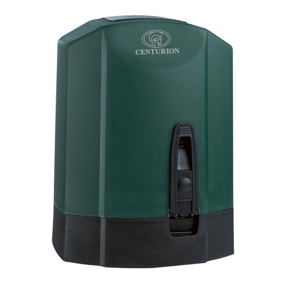
Centurion D10 Installationshandbuch - Seite 7
Blättern Sie online oder laden Sie pdf Installationshandbuch für Toröffner Centurion D10 herunter. Centurion D10 12 Seiten. Industrial sliding gate operators
Auch für Centurion D10: Konfigurationshandbuch (13 seiten), Installationshandbuch (12 seiten), Schnellstart-Handbuch (8 seiten)

Route cables and secure foundation plate
1.
Route cables as determined
in Section 9: Cabling
requirements.
2.
The cable conduits or
SWA cable glands should
terminate onto the cable
termination flange provided
in the foundation plate, as
depicted in the illustration
3.
Make sure that all cables
protrude at least 500mm
from the cable termination
flange.
If bolting the foundation
plate, the left-hand
concrete anchor may need
to be broken off in order to
clear incoming conduits
Make sure that the M10
bolts, which secure the
gearbox, are in place
1.
Insert M8 captive nuts for the
jacking screws as shown.
2.
Screw the M8 grub screw
jacking screws into the
captive nuts.
3.
Adjust jacking screws to give
4-6 mm chassis foundation
plate clearance.
A 4mm Allen key with
"ball end" is handy
Mount the steel rack
The rack must be securely
mounted to the side of the
gate. It must be parallel
with the gate rail, and
there must be a 2 - 3mm
gap between the teeth of
the pinion and the rack,
along the entire travel of
the gate
1.
Fix rack using the steel angle
brackets provided.
2.
Brackets must be spaced no
more than 300mm apart.
3.
When joining different
lengths of steel rack, a
simple way of ensuring
correct pitch spacing, is to
clamp a small off-cut
between the two pieces.
500mm
M10
mounting
bolts
M8 captive nuts
3mm
tooth gap
±300mm
Cable
termination
flange
Jacking
Screw
4-6mm
±300mm
