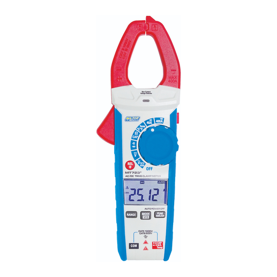
Major tech MT723 Gebrauchsanweisung - Seite 12
Blättern Sie online oder laden Sie pdf Gebrauchsanweisung für Messgeräte Major tech MT723 herunter. Major tech MT723 16 Seiten. Ac/dc trms clamp meter

7.6. Resistance
1. lnsert the black test lead into the negative COM terminal and the red
test lead into the V
2. Set the function switch to the Ω
3. Touch the test probe tips across the circuit or component under test.
4. Read the resistance on the LCD display.
7.7. Temperature Measurements
1. Set the function switch to the TEMP position.
2. lnsert the Temperature Probe into the negative COM and the
CAP TEMP Hz% Ω positive jacks, observing polarity.
V
3. Touch the Temperature Probe head to the device under test.
Continue to touch the part under test with the probe until the
reading stabilizes.
4. Read the temperature on the display. The digital reading will indicate
the proper decimal point and value.
5. Use the MODE button to select °F or °C.
WARNING: To avoid electric shock, be sure the thermocouple
probe has been removed before changing to another measurement
function.
7.8. Diode Test
1. lnsert the black test lead banana plug into the negative COM jack
and the red testlead banana plug into the V·
· Ω positive jack
2. Turn the function switch to Ω
to select the diode function if necessary (diode symbol will appear
on the LCD when in Diode test mode)
3. Touch the test probe tips to the diode or semiconductor junction
under test. Note the meter reading
4. Reverse the test lead polarity by reversing the red and black leads.
Note this reading
5. The diode or junction can be evaluated as follows:
• If one reading displays a value (typically 0.400V to 0.900V) and
the other reading displays OL, the diode is good.
• If both readings display OL the device is open.
• If both readings are very small or '0', the device is shorted.
12
CAP TEMP Hz% positive terminal.
position.
position. Use the MODE button
·CAP·TEMP·Hz%
