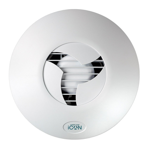
Airflow iCON15 Installations- und Betriebshandbuch - Seite 3
Blättern Sie online oder laden Sie pdf Installations- und Betriebshandbuch für Fan Airflow iCON15 herunter. Airflow iCON15 9 Seiten. Domestic ac fans – 230v

- 1. Installation/Maintenance/Use
- 2. Front Cover Removal
- 3. Mechanical Installation
- 4. Recessing Fans in the Wall
- 5. Surface Mounting Fans on Wall
- 6. Recessing Fans in Ceiling
- 7. Surface Mounting Fans on Ceiling
- 8. Electrical Installation
- 9. Optional Modules for Icon/Eco 230V
- 10. Troubleshooting Tip
- 11. Maintenance
- 12. Warranty
- 13. Range of Optional Modules
The Fan requires a 230V 50Hz single phase supply. Class II equipment. BS EN 60417. An
external 3A fuse is required for each fan unit.
Note: Switches for fans should be selected and sited in accordance with BS7161:2008
All electrical installation to be carried out by an approved electrician in accordance with Part
"P" U.K. Building Regulations and to the latest IEEE standards, or the appropriate regulations
in the country of installation.
ALWAYS ISOLATE THE POWER SUPPLY UNIT AND FAN UNIT FROM THE POWER SUPPLY
BEFORE REMOVING THE COVER.
Mechanical Installation
iCON Domestic Fan can be recessed in a wall or
ceiling. A mounting skirt is provided for surface
mounting the iCON 30 and iCON 60.
To avoid the backflow of condensation into the fan
in a ceiling installation it is good practice to fit a
CONDENSATION TRAP to the outlet duct of the fan.
Ensure free running of the fan impeller and that
flexible duct connections are not over tightened to
the fan outlet spigot.
Airflow recommend that rigid ducting is used
instead of flexible ducting, this will ensure
maximum performance
Front Cover Removal
UNDO THE RETAINING
SCREW AT THE BOTTOM
EDGE OF COVER USING A
.
SCREWDRIVER
CONDENSATION
TRAP
The front cover fan has a bayonet type
fitting. To remove, undo the retaining
screw at the bottom edge of the cover
using a screwdriver, then rotate the
cover a few degrees anticlockwise and
remove. To refit, reverse the above
procedure.
Page 3 of 8
