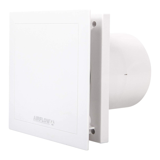
Airflow QuietAir QT 100T Installations- und Betriebsanleitung - Seite 5
Blättern Sie online oder laden Sie pdf Installations- und Betriebsanleitung für Fan Airflow QuietAir QT 100T herunter. Airflow QuietAir QT 100T 8 Seiten. 100mm axial fan
Auch für Airflow QuietAir QT 100T: Installations- und Betriebsanleitung (5 seiten)

Model_QT_100T 27/05/2009 16:51 Page 1
Installation and Operation Instructions
WARNING
CHAPTER 2
SCOPE OF DELIVERY AND
ASSEMBLY
CHAPTER 3
MOUNTING
NOTE
NOTE
1.10 Electrical connection
All work must be carried out with the equipment fully isolated from the power supply. The electrical connection
are to be carried out in accordance with the relevant wiring diagram and are only to be done by a certified elec-
trician. The electrical connection must be fully isolated from the supply up to the final assembly !
All relevant safety regulation, national standards and norms are to be adhered to. An appliance is required for cut off
from the supply with a minimum of 3 mm contact opening of each pole.
The rated voltage and frequency must correspond with the data on the type plate. The insertion of mains supply cable
is carried out via a cable grommet which is included in the delivery. Never lead cable over sharp edges. The equipment
corresponds to protection IPX5 (jet water-protected).
In addition, they correspond to the safety class II.
1.11 Overview of type.
with timer overrun and interval operation
QuietAir 100T
1.12 Accessories (optional)
Wall switch 0-1-2
Cavity wall kit 100mm diameter. Rigid duct with exterior wall grille (white)
Flexible duct kit 100mm diameter x3m long, with exterior wall grille (white)
2.0
Scope of delivery / packing unit
Leave the fan in its box until installation. Check that the fan is in good condition and has not been damaged in transit.
4
2
8
1
3.0
Preparation for wall or ceiling installation (surface mounted)
The assembly and start-up of the fan unit should be carried out first after finishing all other work and after the final
cleaning in order to avoid damage and contamination of the fan unit.
The position of the cable exit is variable (see fig.2/3).
fig.2
Cable exit in
the dark
section
user-defi-
ned.
min. 90 mm
3.1
Cable exit from the wall
- Distance to the duct centre depending on cable exit 58 mm with a variable position under the casing.
- For a simple assembly an exit is recommended as shown (turnable by 90° in each case).
The optimal position is 45° each if the cable exit is directly at the position of the cable grommet.
- Duct inside diameter 100 mm and distance to room corners: at least 90 mm
3.2
Drill holes
- Set casing against the wall, mark the holes and drill. Fasten with at least 2 screws and plugs. For surface installation
the casing is provided with a side entry knockout (Fig.5, Pos.1) for the cable ! The mains supply cable is to be kept in
such a way that no ingress of moisture is made possible along the cable.
fig.1
1.
Fascia
6
Cover of control board including 2 x fastening screws
2.
3.
Electronic control board
Casing with impeller
4.
Guide vane removable at reduced installation depth
5.
6.
Removable back draught shutter
5
Ð
Cable grommet
7.
Assembly kit
7
2 x screws with plugs for wall mounting
4
fig.3
Recommen-
ded cable exit
Cable runs under the casing. Cable
optional 0...-
length from the wall at least 180 mm.
360 °, ideally
in each case
45 °
Drill holes
2
Ref:no. 71523101
Ref:no. 72643202
Ref:no. 72643602
